
Related Manuals for QSFPTEK S7300-48TE4X2Q


Summary of Contents for QSFPTEK S7300-48TE4X2Q
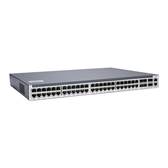
- Page 1 S7300-48TE4X2Q Quick Start Guide V2.0 48-Port Multi-Gigabit Ethernet L3 Switch 48x 100M/1000M/2.5GBASE-T Ports, with 4x 1G/10G SFP+ and 2x 40G QSFP+ Uplinks, Support BGP www.qsfptek.com V2.0 1 / 10...
- Page 2 Introduction The QSFPTEK S7300-48TE4X2Q multi-gigabit L3 switch has 48x 100M/1000M/2.5GBASE-T RJ45 ports and 4x 10G and 2x 40G uplinks. S7300-48TE4X2Q is an access layer switch for high-end campuses, enterprise branches and SMB networks. With high-density 2.5G Ethernet ports for directly connecting gaming computers, S7300-48TE4X2Q is popular for deployment in the e-sports industry, such as high-end Internet cybercafes, gaming hotels, E-sports arenas, etc.
-
Page 3: Hardware Overview
10/40G port link. Green 10/40G packets receiving or (Breakout) Blinking transmitting. If the SYS indicator flickers, the SYS LED system works normally. If the PWR indicator is always PWR LED on, the device is powered on. www.qsfptek.com V2.0 3 / 10... - Page 4 discharged Avoid damaging devices by following the electrostatic discharge prevention procedure. S7300-48TE4X2Q Hardware Installation Manual Put the machine box in a place where cool air can blow off the heat inside the machine box. Make sure the machine box is sealed.
- Page 5 Connecting the Power Plug the AC power cord to the switch power port on the back rear. Connect the other end of the power cord to an AC power source equipment. Connecting the RJ45 Ports www.qsfptek.com V2.0 5 / 10...
- Page 6 Insert the SFP+ module into the SFP+ port. Plug a fiber patch cable into the SFP+ transceiver. Connect the other end of the fiber to the device that you want to realize data communication. www.qsfptek.com V2.0 6 / 10...
-
Page 7: Connecting The Management Ports
Insert the RJ45 connector of the console cable into the console port on the switch. Connect the D89 female connector on the other end of the console cable to the serial port www.qsfptek.com V2.0 7 / 10... -
Page 8: Configuring The Switch
255.255.255.0. Step 3: Open a web browser and type http://192.168.0.2 in the address bar. Enter the default username and password (admin/admin). Step 4: Click sign-in to access the web-based configuration page. www.qsfptek.com V2.0 8 / 10... -
Page 9: Troubleshooting
1. Power and cooling systems—power and fan Port, cable and connection—ports on the front panel of the switch and the cables connecting these ports Faults Relative to Power and Cooling System Do the following checkups to help remove the fault: www.qsfptek.com V2.0 9 / 10... -
Page 10: Support And Other Resources
Product Warranty S7300 series switches are backed by a 5-year limited warranty supported by QSFPTEK. You are eligible to apply for a return within 14 days and exchange within 90 days of receiving them. For more details about applying qualifications, please live chat or email sales@qsfptek.com...
Need help?
Do you have a question about the S7300-48TE4X2Q and is the answer not in the manual?
Questions and answers