
Related Manuals for Rockwell Automation Allen-Bradley 1753-OW8


Summary of Contents for Rockwell Automation Allen-Bradley 1753-OW8
-
Page 1: Table Of Contents
Installation Instructions GuardPLC Relay Output Module Catalog Number 1753-OW8 Topic Page Important User Information About the 1753-OW8 Relay Output Module General Safety Install the Module Mount the Module Ground the Module Wire the Module Make Safety-related Communication Connections Reset Push Button Status Indicators Specifications Additional Resources... -
Page 2: Important User Information
In no event will Rockwell Automation, Inc. be responsible or liable for indirect or consequential damages resulting from the use or application of this equipment. -
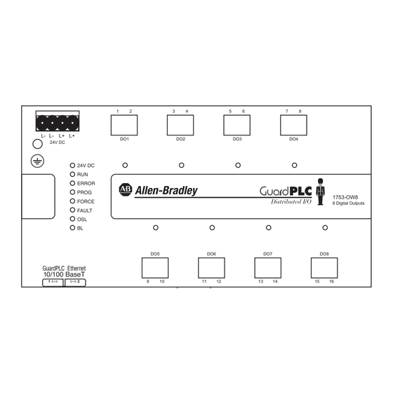
Page 3: About The 1753-Ow8 Relay Output Module
Do not touch connectors or pins on component boards. • Do not touch circuit components inside the equipment. • Use a static-safe workstation, if available. • Store the equipment in appropriate static-safe packaging when not in use. Rockwell Automation Publication 1753-IN012C-EN-P - June 2010... -
Page 4: Install The Module
Follow these steps to install the 1753-OW8 module. 1. Mount the module to a DIN rail. 2. Ground the module. 3. Wire the module. 4. Make communication connections. This publication describes these steps in detail. Rockwell Automation Publication 1753-IN012C-EN-P - June 2010... -
Page 5: Mount The Module
Use the transparent label shipped with the module to note the IP Address and System ID (SRS). If you attach the label to the module, make sure you do not cover any of the IMPORTANT ventilation slots. Rockwell Automation Publication 1753-IN012C-EN-P - June 2010... -
Page 6: Ground The Module
L- terminals are internally connected, so you can daisy-chain 24V DC power from the module to other devices in the panel by using the remaining terminal. ATTENTION: Do not reverse the L+ and L- terminals or damage to the module will result. There is no reverse polarity protection. Rockwell Automation Publication 1753-IN012C-EN-P - June 2010... - Page 7 DC switching capacity. Errors in one or more channels are indicated by the FAULT status indicator. In addition, the system status can be evaluated in the user program. Rockwell Automation Publication 1753-IN012C-EN-P - June 2010...
-
Page 8: Make Safety-Related Communication Connections
RSLogix Guard PLUS! software. The media access control (MAC) address of the module is printed on the label positioned over both lower RJ45 connections. Rockwell Automation Publication 1753-IN012C-EN-P - June 2010... -
Page 9: Reset Push Button
The next time you cycle power, these settings will be restored to the last values stored into nonvolatile memory. This means that either the settings prior to the reset will be restored, or if any settings were changed after the reset, those new settings will still be in effect. Rockwell Automation Publication 1753-IN012C-EN-P - June 2010... -
Page 10: Status Indicators
Boot Loader unable to load operating system or unable to start COMM operating system loader. Module status can be interrogated through the programming software. For more information, refer to the GuardPLC System User Manual, publication 1753-UM001. Rockwell Automation Publication 1753-IN012C-EN-P - June 2010... -
Page 11: Specifications
Meets IP20 Width, approx. 207 mm (8.14 in.) including housing screws Height, approx. 114 mm (4.49 in.) including latch Depth, approx. 86 mm (3.38 in.) including grounding bolt Weight, approx. 1.3 kg (3.47 lb) Rockwell Automation Publication 1753-IN012C-EN-P - June 2010... - Page 12 ≤ 0.1 switching cycles Service life, electrical per second Use this Conductor Category information for planning conductor routing. Refer to Industrial Automation Wiring and Grounding Guidelines, publication 1770-4.1. Rockwell Automation Publication 1753-IN012C-EN-P - June 2010...
- Page 13 10V rms with 1 kHz sine-wave 80% AM from • 150 kHz…80 MHz IEC 61000-4-6 • Damped Oscillatory Wave Immunity ±1 kV line-earth (CM) on signal ports • • IEC 61000-4-12 ±1 kV line-earth (CM) on power ports Rockwell Automation Publication 1753-IN012C-EN-P - June 2010...
- Page 14 : up to and including SIL 3 according to IEC 61508 and PLe (Cat. 4) according to ISO 13849-1 See the Product Certification link at http://www.ab.com for Declarations of Conformity, Certificates, and other certification details. When used with specified firmware revisions. Rockwell Automation Publication 1753-IN012C-EN-P - June 2010...
-
Page 15: Additional Resources
General guidelines for installing a Rockwell Automation industrial system Guidelines, publication 1770-4.1 You can view or download publications at http://www.rockwellautomation.com/literature. To order paper copies of technical documentation, contact your local Rockwell Automation distributor or sales representative. Rockwell Automation Publication 1753-IN012C-EN-P - June 2010... - Page 16 Rockwell Automation representative. New Product Satisfaction Return Rockwell Automation tests all of its products to ensure that they are fully operational when shipped from the manufacturing facility. However, if your product is not functioning and needs to be returned, follow these procedures.
Need help?
Do you have a question about the Allen-Bradley 1753-OW8 and is the answer not in the manual?
Questions and answers