
Related Manuals for LEMKEN SOLITAIR 23+


Summary of Contents for LEMKEN SOLITAIR 23+
- Page 1 OPERATING INSTRUCTIONS FRONT TANK SOLITAIR 23+ en-GB | Item no. 17517449 | BA 00/2023-12...
- Page 2 Pass these instructions to all users / owners. Original instructions © 2023 | This documentation is copyright protected. The copyright remains with LEMKEN GmbH & Co. KG, Weseler Strasse 5, D-46519 Alpen. The texts, diagrams and drawings must not be duplicated, distributed or disclosed in any other way,...
-
Page 3: Table Of Contents
Table of contents Table of contents About these instructions............................1 1.1 Introduction................................. 1 1.2 Target groups..............................3 1.3 Applied presentations............................. 3 1.3.1 Signal words and hazard statements...................... 3 1.3.2 Symbols and text markings........................4 1.3.3 Direction specifications..........................4 1.4 Further applicable documents........................5 Safety.................................... - Page 4 Table of contents 4.3 Attaching the machine..........................48 4.3.1 Attaching the machine to a tractor....................... 48 4.3.2 Adapting machine connection....................... 51 4.3.3 Mounting connecting hoses........................54 4.3.4 Operating combination machines......................55 4.4 Checking field of view........................... 58 4.5 Preparing the machine for use........................59 4.5.1 Preparations..............................
- Page 5 Appendix................................. 124 A Type plate variants............................125 B Tightening torques screws .......................... 126 C LEMKEN overview of operating materials....................131 D Calculation of axle load and ballasting for mounted machines............. 133 E Cross shaft overview............................137 en-GB | Item no. 17517449 | BA 00/2023-12...
- Page 6 Table of contents en-GB | Item no. 17517449 | BA 00/2023-12...
-
Page 7: About These Instructions
About these instructions About these instructions Introduction These operating instructions are important and belong to the machine's scope of delivery. These operating instructions must be available to the user at the place of use. Always read chapter "Safety" before using the machine for the first time. - Page 8 About these instructions Validity range These operating instructions describe operation of the machine after initial commissioning by the LEMKEN sales partner and handover to the operator. Prior to operation, initial commissioning and instruction in operation, setting/adjustment and maintenance must have been carried out.
-
Page 9: Target Groups
About these instructions Target groups The target groups of these operating instructions are operators, users and service personnel of the machine. The target groups must meet the requirements for operators, users and service personnel as defined in these instructions. INFORMATION Ä... -
Page 10: Symbols And Text Markings
About these instructions 1.3.2 Symbols and text markings Symbol, text Meaning marking In front of and in texts Marking for routine maintenance tasks ● Activities that demand the help of service staff. Listing Position numbers [1], Example: ‘Settings’ Software element Example: [OK] Softkey, key, switch and button [kg]... -
Page 11: Further Applicable Documents
Manufacturer’s instructions on using seeds Latest versions of the LEMKEN docu‐ ments The latest versions of the LEMKEN documents can be found in the LEMKEN Online Information System (LEONIS). Users can access LEONIS via the QR code or the LEMKEN website. -
Page 12: Safety
Safety Safety Machine limits Intended use The machine is used for sowing on agricultural land. The machine is used for distributing granulated fertiliser on agricultural land. The machine can be combined with other suitable machines according to the instructions in this manual, chapter Ä... -
Page 13: Requirements Of Operators, Users And Service Personnel
Safety Hazardous area The machine and the area in the immediate vicinity of the machine is deemed a hazardous area. This includes the space over the entire width, length and height of the machine, as well as an additional safety distance of two metres to the machine. -
Page 14: General Safety Information
Safety Qualified specialists For the purposes of these instructions, qualified specialists are all per‐ sons who, on the basis of their professional training and experience, carry out the tasks assigned to them in a professional manner. Qualified specialists have knowledge of the relevant standards and regulations, recognise possible hazards and avoid hazards independently. - Page 15 Safety Spare parts Permissible spare parts are available from agroparts. The QR code takes the user directly to agroparts. There, the user can find spare parts for the machine. Safety equipment Existing and fully functional safety devices protect against death or serious personal injury.
- Page 16 Safety Hydraulic assembly The hydraulic assembly might be under high pressure. Hydraulic oil leaking under pressure can penetrate through the skin into the body. Injury to body parts, face, eyes and unprotected skin may result. The hydraulic assembly may be hot. The hydraulic oil is harmful to health.
-
Page 17: Safety Information On Hazardous Areas Of The Machine
Safety Safety information on hazardous areas of the machine Area between the tractor and When standing between the tractor and machine, there is a risk due to machine tractor movements or sudden machine movements. Secure the tractor against rolling away. ►... - Page 18 Safety Moving hazardous area The hazardous area of the machine during operation. Moving hazardous area The hazardous area includes the area in driving direction across the entire width of the machine. There must be NO persons in the hazardous area. If there are persons in the hazardous area, may result in death or injury to persons.
- Page 19 Safety Climb and descend with your face towards the machine. ► NEVER use control elements as a handle. Control elements may be ► actuated accidentally and trigger functions that pose a danger. NEVER jump off the machine. ► NEVER climb onto a moving machine. ►...
-
Page 20: Safety Information On Structural Modifications
Safety Safety information on structural modifications Structural modifications Structural modifications and extensions can impair the functionality and operational safety of the machine. This may result in death or injuries. Auxiliary equipment and spare parts must comply with the manufactur‐ er's requirements. Modifications and conversions may only be carried out with the ►... - Page 21 Safety Behaviour during flashover of over‐ Flashovers cause high electrical voltages on the outside of the tractor- head lines machine combination. Large voltage differences occur on the ground around the tractor-machine combination. Large steps, lying down or supporting yourself on the ground may cause life-threatening electrical currents (step voltage).
-
Page 22: Safety Information On Hazardous Substances
Safety Road travel The user operates the machine via control elements such as tractor control units, touch screen, buttons or joystick. Touching the control elements may trigger functions and machine movements, even if touching the control elements was not intended. Disabling machine functions before driving on the road. -
Page 23: Design And Description
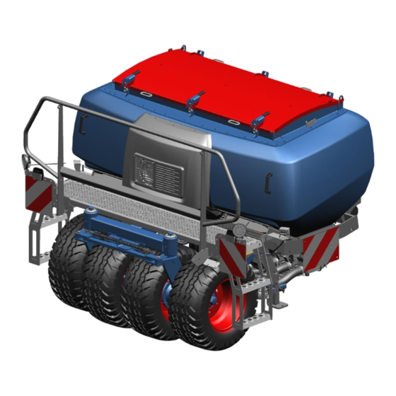
Design and description Design and description Machine overview INFORMATION The machines can be equipped differently at the factory. – Standard components, special equipment or optional accessories are not marked separately. – Contents in this document may differ from the actual equipment of the machine. - Page 24 Design and description Hopper Metering unit Cover Additional weights Work lighting Stand Step, platform Headstock Type plate en-GB | Item no. 17517449 | BA 00/2023-12...
- Page 25 Design and description Camera Lighting equipment Tyre packer roller Type plate The machine is marked with a type plate. The machine type can be identified uniquely by the type plate. Further information about the type plate: Ä Appendix A ‘Type plate variants’...
-
Page 26: Machine Safety
Design and description Machine safety 3.2.1 Position of the label 3.2.2 Meaning of the labels This section explains the information and warning signs that have been affixed to the machine. Reading the operating instructions Incorrect use or operation of the machine can result in death or serious injury. - Page 27 Design and description Turn off the engine A tractor with the engine running can cause unintentional movements. This may even be fatal or result in serious injuries. Before maintenance and repair work: Turn off the engine. ► Engage the parking brake of the tractor. ►...
-
Page 28: Safety Devices
Design and description Hydraulic equipment Connection overview of hydraulic hoses P6 - Supply lines T6 - Flow control valve: Return line, pressureless T - Return line, pressureless 3.2.3 Safety devices 3.2.3.1 Lighting equipment and identification The marking and the lighting equipment increase safety while driving on the road. - Page 29 Design and description 3.2.3.2 Stabilisation The stands are required for parking and moving the machine safely. Each stand is always secured via a pin with a linch pin. The stand is removed after attachment of the machine. Machine with tyre packer roller Stand, with steerable brake roller Machine without tyre packer roller Stand, with steerable brake roller...
-
Page 30: Headstock
Design and description 3.2.3.4 Safety chain For machines without a braking system, a safety chain may be required, depending on the national regulations. ATTENTION – Use the safety chain only as a safety device. Headstock Top link pin The headstock with cross shaft and top link pin has been Cross shaft... -
Page 31: Hopper For Seeds And Fertiliser
Design and description Steering assembly Steering assembly The steering assembly of the tyre packer roller allows easy cornering. (20° steering angle, 10° each direction) The steering system can be locked for better directional stability. Scraper Scraper The tyre packer roller is equipped with scrapers . - Page 32 Design and description Cover Machine without pressure system Cover The machine is equipped with a roller tarpaulin cover (not shown). The cover is attached to the hopper with lashing straps. Machine with pressure system The machine is equipped with a pressure-resistant steel cover Screen Screen The split screen...
- Page 33 Design and description The fan is hydraulically driven and mounted on the hopper. The air flow from the fan transports the seeds or fertiliser to the distrib‐ utors of the coulter bar. The setting is made via the control unit of the tractor or via the flow control valve of the machine.
-
Page 34: Metering
Design and description Camera monitoring Camera The camera system consists of two cameras. The cameras capture Holder the lower field of view in front of the machine. Holders are mounted on brackets on both sides of the hopper for mounting the cameras. Metering Metering unit Metering consists of several metering units... - Page 35 Design and description Metering units Motor Each metering unit is equipped with a motor . The motors can be activated separately. Coupling piece Alternatively, two metering units are connected to a coupling piece which are controlled together via a motor. en-GB | Item no.
- Page 36 Design and description Pressure system equipment The pressure system is used to increase the flow rate. The machine is equipped with: Locking latch Pressure-tight steel cover with three locking latches Metering unit Sealed metering units No hopper ventilation: Air distributor to the hopper is closed with a Protecting cap protecting cap en-GB | Item no.
- Page 37 Design and description Injector equipment The machine is equipped with: Metering unit Exhaust air hose Roller tarpaulin cover Metering units with exhaust air hose (for use with fertiliser) Screen grid Screen grid (for use with seeds) INFORMATION NEVER use the screen grid with fertiliser. Protecting cap No hopper ventilation: Air distributor to the hopper is closed with a protecting cap...
- Page 38 Design and description Use: Seeds or fertiliser The metering wheel unit consists of six metering wheels per metering unit: One fine metering wheel Two narrow metering wheels Three wide metering wheels Universal metering wheel unit Use: Fertiliser The metering wheel unit consists of four metering wheels per metering unit: Four wide metering wheels Fertiliser metering wheel unit...
-
Page 39: Step And Platform
Operation 3.8.1 Operation terminal LEMKEN machines with electronic control are operated via an opera‐ tion terminal in the tractor. INFORMATION Some machine functions cannot be operated via the operation terminal. These functions are operated for example via the control centre on the machine. -
Page 40: Additional Input Devices
Design and description LEMKEN ISOBUS operation terminal The machine control is operated via an ISOBUS operation terminal, e.g., LEMKEN CCI 1200. INFORMATION Depending on the machine type, another input device may be necessary for operating all the functions, e. g.: –... - Page 41 8 functions. The side switch can be used to select 3 button levels. The LEMKEN multifunctional handle can be freely assigned with 24 ISOBUS functions. Possible to switch between ISOBUS AUX-N (AUX-2) and AUX-O (AUX-1)
-
Page 42: Commissioning
Commissioning Commissioning Preparing an attachment 4.1.1 Checking suitability of the tractor WARNING Risk of accident due to unsuitable tractor If the tractor is not suitable for the machine, compo‐ nents of the machine may be overloaded and the tractor- machine combination may not be steered safely. This may result in accidents with injuries or death of persons or damage to the machine. - Page 43 Commissioning Assembly group Requirement Check The categories of the three-point linkage of the tractor match the Ä Chapter 12.10 ‘Con‐ categories of the cross shaft or the lower link pin and the top link pin. necting systems at the If the categories differ, the three-point linkage of the tractor or the machine’...
-
Page 44: Preparing Tractor
Commissioning 4.1.2 Preparing tractor 4.1.2.1 Checking power supply A supply voltage of 12 V is required for the electronic control. The entire electronic control is supplied with power via the power supply cable. INFORMATION To ensure a good energy flow, electric contact surfaces must be clean. - Page 45 Commissioning Tractor without flow control valve Equipment Single acting Double acting Pressureless Colour Code spool valve spool valve return line Fan drive Supply: yellow Return: white Hydraulic metering stop Operation with coulter bar or precision seed drill Connection fan drive Connection coulter bar Connection fan drive Connection coulter bar...
- Page 46 Commissioning Tractor with flow control valve Equipment Single acting Double acting Pressureless Colour Code spool valve spool valve return line Fan drive Supply: yellow Return: white Return: white Operation with coulter bar or precision seed drill Connection fan drive Flow control valve Connection fan drive Connection coulter bar Connection coulter bar...
-
Page 47: Preparing The Machine For Use
Scope of delivery and equipment of the machine may vary depending on the configuration of the purchase order. 1. Make certain that all LEMKEN original parts are present according to the purchase order. 2. Make certain that all parts are undamaged and correctly mounted (see corresponding mounting instructions if applicable). - Page 48 Commissioning INFORMATION Identical metering wheel units must be installed in all the metering units. – Perform a calibration test after replacement. Accessibility to the metering wheel When ballasting with five sets of weights or more, accessibility to the units middle metering devices may be limited. 1.
- Page 49 Commissioning Preparing metering wheel units 1. Remove the cover. Cover 2. Screw in the stop screws until the stop screws no longer pro‐ trude beyond the metering wheels. Ä Chapter 4.5.5 ‘Adjusting and checking metering wheels’ on page 66 Ä ‘Switching on metering wheel’...
- Page 50 Commissioning Removing metering wheels 1. Metering unit without coupling piece: Remove the linch pin of the gear wheel. Linch pin 2. Metering unit with coupling piece: Remove the M5 screw Screw - M5 en-GB | Item no. 17517449 | BA 00/2023-12...
- Page 51 Commissioning 3. Remove the gear wheel and the washer from behind the gear wheel. Washer 4. Pull out the metering shaft For Mega Plus metering wheel unit: A combined pull/twist motion is required as the paddles protrude. Metering shaft 5. Remove the complete metering wheel unit 6.
- Page 52 Commissioning Attaching metering wheels 1. Thread on the desired metering wheel unit Alternatively, provide the pre-assembled metering wheel unit on a metering shaft. Metering wheel unit 2. For Mega Plus metering wheel unit: Make sure that there are two shims between the middle metering wheels.
- Page 53 Commissioning 6. Check the metering wheels. The screws must be visible. It must be possible to move deactivated metering wheels smoothly. The total axial clearance with a metering wheel unit mounted ready for use may be a maximum of 0.5 mm between the middle shims , for example.
-
Page 54: Attaching The Machine
Commissioning 11. Mount the cover 12. After attachment of the machine: Adjust and check the metering wheels. Ä Chapter 4.5.5 ‘Adjusting and checking metering wheels’ on page 66 Ä ‘Switching on metering wheel’ on page 67 Ä ‘Switching off metering wheel’ on page 68 Ä... - Page 55 Commissioning 3. Make sure that the pin is mounted and secured by a peg 4. Prepare the lower links of the tractor for attachment of the machine: Adjust the distance of the lower links. Lower the lower link. If the lower links allow for lateral movement: Secure the lower links against lateral movement.
- Page 56 Commissioning 17. Remove all the stands from the supports of the basic frame 18. Store the stands securely. Basic frame 19. Adjust the motor speed using one of the following options: Stand Spool valve on the tractor Flow control valve INFORMATION: Observe the tractor documents.
-
Page 57: Adapting Machine Connection
Commissioning 4.3.2 Adapting machine connection Checking machine connection When attaching the machine to the tractor for the first time: 1. Attach the machine. 2. Make sure that there is sufficient clearance between the machine and the tractor for mounting. 3. If the clearance for mounting is insufficient: Turn the front wheels of the tractor. - Page 58 Commissioning Adapting cross shaft If there is insufficient clearance on the lower links of the tractor: 1. Reverse the tractor 1 m. 2. Secure the tractor against rolling away. 3. Switch off the tractor engine. 4. Remove ignition key. 5. Release the clamping screws at both stops.
- Page 59 Commissioning 5. If the machine cannot be aligned horizontally: Change the position of the headstock plates on the machine. Ä ‘Changing position of the tower plates’ on page 53 Change the attachment point of the top link on the machine. Ä...
-
Page 60: Mounting Connecting Hoses
Commissioning 4.3.3 Mounting connecting hoses Observe the connection direction of the hoses The connecting hoses are electrically conductive. A printed arrow indi‐ cates the direction of flow. INFORMATION If the connection directions are reversed, the machine will not function. Connecting front machine The coupling parts of the connecting hoses are attached to the bracket of the hopper using a holder. -
Page 61: Operating Combination Machines
Commissioning Connecting rear machine 1. Guide the connecting hoses along the tractor in the pre-assembled holder to the rear machine. 2. Connect the connecting hoses to the distributors of the rear machine. ð The front machine and the rear machine are connected via the connecting hoses. - Page 62 Commissioning Coulter bar OptiDisc 25 Required Number of Number of Number of metering unit metering units sections level sensors Coulter bar with two dis‐ tributors Coulter bar with four distributors en-GB | Item no. 17517449 | BA 00/2023-12...
- Page 63 Commissioning Connecting combination machine Additional components are required for distribution, e.g. OptiDisc com‐ bination with a seed drill. INFORMATION Observe other applicable documents. Ä Chapter 1.4 ‘Further applicable documents’ on page 5. 1. Ensure that all the connections and hydraulic hoses are pressure‐ less and empty.
-
Page 64: Checking Field Of View
Commissioning Checking field of view Reference point Preconditions: Projection point √ Front mounted machine is mounted. Bearing point √ The tractor/machine combination is located on a level surface. Driving surface Distance from front edge of front mounted machine to the middle of the steering wheel √... -
Page 65: Preparing The Machine For Use
Commissioning WARNING If the distance from the front edge of the front mounted machine to the middle of the steering wheel is greater than 3.50 m: Use suitable measures to compensate for the restricted field of view at exits from the yard, road access points and road intersections, for example: –... - Page 66 Commissioning 4.5.2.1 Adjusting fan speed Required fan speed Distribution Required speed [rpm] Injector Pressure system Grass 3000 3000 Remaining fine seeds 4000 4000 Cereals 4500 4500 Peas and beans 5500 5500 Fertiliser 5500 4500 INFORMATION Higher speeds will result in improved longitudinal distri‐ bution and cross distribution and in lower delay times.
- Page 67 Commissioning Adjustment using add-on spool valve without volumetric flow control Precondition: √ The oil of the hydraulic system is at operating temperature. 1. At the machine: Completely close the flow control valve 2. In the tractor cab: Switch on the add-on spool valve for the fan drive.
- Page 68 Commissioning Adjustment using add-on spool valve with volumetric flow control Precondition: √ The oil of the hydraulic system is at operating temperature. 1. At the machine: Open the flow control valve fully. 2. In the tractor cab: Set the desired speed or the mbar range via the volumetric flow control adjustment of the add-on spool valve.
-
Page 69: Adjusting Level Monitoring
Commissioning 4.5.2.2 Checking back pressure of the pressureless return For each tractor-machine combination: 1. Make sure the maximum back pressure at the fan is 3 bar. 2. If necessary, measure the back pressure or have it measured. Note on measurement: Measure at the first interface to be disconnected without tools as viewed from the fan Measure at operating temperature... -
Page 70: Adjusting Agitator Shaft
Commissioning 4.5.4 Adjusting agitator shaft To prevent clogging or clumping, each metering unit is fitted with an Agitator shaft agitator shaft For delicate seeds: The agitator shaft should be switched off. For robust seeds: The agitator shaft should be switched on. Preparation for machines with four metering units Remove the protection shield . - Page 71 Commissioning Switching off agitator shaft 1. Remove the linch pin from the gear wheel of the agitator shaft. 2. Insert the linch pin into the hole of the agitator shaft for safe keeping. 3. If necessary, mount a protection shield . Agitator shaft Gear wheel Linch pin...
-
Page 72: Adjusting And Checking Metering Wheels
Commissioning 4.5.5 Adjusting and checking metering wheels INFORMATION The adjustments for all the metering units must be iden‐ tical. – Perform a calibration test after the adjustment and the check. The adjustment of the metering wheels is displayed on the operation terminal at the start of the calibration test. - Page 73 Commissioning 2. Screw in or unscrew the stop screws with the corresponding tool. 3. To switch the metering wheels on and off: Universal metering wheel unit: Screw in or unscrew the stop screws using an 8 mm socket wrench and a 3 mm Allen key. Fertiliser metering wheel unit: Screw in or unscrew the stop screws using an 8 mm socket wrench.
- Page 74 Commissioning Switching off metering wheel 1. Unscrew the stop screw until it is level with the locking plate ð The stop screw rests on the locking plate INFORMATION: Universal metering wheel unit, fertiliser metering wheel unit – The screw head of the stop screw must be located above the plastic cover.
- Page 75 Commissioning Checking metering wheel adjustment 1. Fertiliser metering wheel unit: The second metering wheel from the right must always be active: Stop screw screwed in Stop screw 2. MegaPlus metering wheel unit: The third metering wheel from the right must always be active: Stop screw screwed in 3.
-
Page 76: Adjusting Bottom Gates
Commissioning 4.5.6 Adjusting bottom gates The adjustment of the bottom gates is displayed on the operation terminal at the start of the calibration test. The position of the bottom gates is determined on the basis of the selected seeds or fertiliser. To ensure gentle distribution, adjustable bottom gates Lever are arranged... -
Page 77: Performing Calibration Test
Commissioning Checking and setting metering start Mechanical lifting sensor The sensor is switched with a tension spring via a chain 1. Attach shackles to the tractor in the area of the top link. ð Longer chain = later metering start. ð... - Page 78 Commissioning Before the calibration test Preconditions: √ Fan speed is below 500 rpm. √ Machine is not moving (no driving speed). √ Machine is lifted. √ Hopper is placed under the metering unit. √ Metering hatches are open. 1. Call up menu. ð...
- Page 79 Commissioning Procedure 1. Select seeds or fertiliser. 2. Enter specific weight of seeds or fertiliser. ð The settings open. The following functions are available: Select fixed value. For an optimum calculation: Determine weight by weighing. Select fixed value 1. Press the option field. ð...
- Page 80 Commissioning Determining weight by weighing Required tools: √ Measuring cup [volume 1 l] Press the option field. ► ð The function for entering the exact hectolitre mass is active. ð The preset value corresponds to the fixed value. Changed values are permanently stored. A changed value is not auto‐ matically reset to the fixed value.
- Page 81 Commissioning Setting up individual seeds or fertil‐ isers The memory locations 1...10 can be freely assigned for your own seeds or fertilisers. Select the desired memory location. ► ð The settings open. 1. Enter name. 2. Enter fixed value [g/l]. 3.
- Page 82 Commissioning 4.6.1.2 Setting target rate of the seeds or fertiliser In the setting parameters: Enter target distribution rate [kg/ha]. ► If the unit of measurement is not available: Convert grains/m kg/ha. Converting distribution rate [grains/m = kg/ha] Open converter. ► ð...
- Page 83 Commissioning 3. Enter germination capacity. The germination capacity specifies the quality of the grains as a percentage which form a seedling. ð The distribution rate is converted on the basis of the cur‐ rently set values and accepted automatically. 4.6.1.3 Setting operating speed 1.
- Page 84 Commissioning Automatic process 1. Follow the display text: Setting positions are being searched for. LED red: Sensor not attenuated LED green: Attenuated sensor 2. Follow the display text: All setting positions have been found. LED green: Attenuated sensor ð The settings for the metering wheels open. 4.6.1.5 Adjusting metering wheels Adjusting metering wheels...
- Page 85 Commissioning Settings in the control Selection LEMKEN recommendation Grey: LEMKEN recommendation is not available User-specific setting Metering wheels Select the mounted metering wheel unit: Universal metering wheel unit Fertiliser metering wheel unit MegaPlus metering wheel unit If necessary, select metering wheels individually...
- Page 86 Agitator shaft Switch off Switch on Procedure LEMKEN recommendation 1. Select LEMKEN recommendation. ð The recommended settings are displayed. 2. Adjust the machine exactly to the settings. User-specific setting If a recommendation is not available, all the metering wheels are switched off to start with.
- Page 87 Commissioning 3. Set metering wheels specific to the user: Use the metering wheel. Do NOT use the metering wheel. 4. Adjust the machine exactly to the settings. Continue process. ► Automatic process 1. Follow and execute the display text: Precondition: Tanks have been placed underneath the metering units.
- Page 88 Commissioning The metering units can be stopped at any time during the calibration time. After stopping, the calibration test can be continued or termi‐ nated. Adjusting calibration time If, for example, the hoppers are filled after a known duration, the cali‐ bration time can be shortened if desired.
- Page 89 Commissioning To repeat the calibration test in case of doubt: Press the button. ► To accept the values: Press the button. ► 4.6.1.8 Terminate calibration test After confirming the operating speed The following page opens: 1. Follow and execute the display text: Close the metering hatches.
- Page 90 Commissioning 4.6.1.9 Saving a calibration test The currently completed calibration test can be saved. If the seeds are changed in the meantime, the calibration test can be subsequently reloaded. 1. Press the softkey. ð The memory locations are displayed. A total of five memory locations are available.
- Page 91 Commissioning 2. Select the desired memory location. ð The values of the selected calibration test open. 3. Confirm your selection. ð The next page opens automatically. 4. Follow the display text: The metering units are checked. A plausibility test is performed: Are the values ok? Does the calibration test match the selected secondary machine (working width)?
-
Page 92: Preparing For Road Travel
Preparing for road travel Preparing for road travel Check and prepare the following assembly groups, safety devices and functions in accordance with these operating instructions before each road travel: Checklist Machine with head‐ Connections of the machine to the The top link pin must be secured. tractor stock The connections of the lower links with the... -
Page 93: Operation
Operation Operation Driving on the headland 1. Before the headland: Lift the machine fully. ATTENTION: If parts of the machine come into contact with the ground, the machine components may be damaged when turning. 2. On the headland: Adapt the driving speed to the actual ground and soil conditions. 3. -
Page 94: Cleaning And Care
Cleaning and care Cleaning and care Cleaning machine Cleaning intervals Recommendation: After every use When there is a seed change After the season CAUTION Dressed seeds Dust from untreated or dressed seeds can result in damage to health. – When cleaning: Wear protective clothing. ATTENTION Damage due to cleaning with a high-pressure cleaner Components may be damaged when cleaning with a... -
Page 95: Emptying Hopper
Cleaning and care Emptying hopper Empty hopper according to property of the distribution via the metering units: Easy flowing distribution can be simply conveyed from the hopper via the bottom gates. For viscous distribution of grain with husk intact the metering wheels can also be driven. -
Page 96: Internal Cleaning
Cleaning and care Using remaining quantity discharge program For a quick discharge: ► Switch on all metering wheels. ð The program is executed via the operation terminal. See operating instructions for the control. After discharge 1. To close the discharge flaps: Hook in the lever and swivel it upwards. - Page 97 Cleaning and care Cleaning and drying further compo‐ nents Cleaning with compressed air or clear water: Ä ‘Cleaning metering unit’ on page 91. Ä ‘Cleaning exhaust air hose’ on page 92. 3. Clean components contaminated with fertiliser dust. Dry the machine: 1.
- Page 98 Cleaning and care Cleaning exhaust air hose Soiled exhaust air hoses impact the delivery rate. ► Clean soiled exhaust air hoses . Ä Chapter 7 ‘Cleaning and care’ on page 88 Exhaust air hose en-GB | Item no. 17517449 | BA 00/2023-12...
-
Page 99: Decommissioning
Decommissioning Decommissioning Detaching machine Detaching machine with headstock Precondition: √ The subsoil is level with sufficient bearing capacity. 1. Secure the tractor and machine to prevent them from rolling away. WARNING: When standing between the tractor and machine, there is a risk of the tractor rolling away or of sudden machine movements. -
Page 100: Storing And Wintering Machine
Decommissioning Storing and wintering machine INFORMATION Before wintering, check the machine according to the lubrication schedule. Apply grease, if necessary. Preconditions: √ Machine is cleaned. 1. Store machine in a frost-free and dark place under cover. ATTENTION: Light (UV radiation) accelerates the ageing process of plastics. -
Page 101: Maintenance And Repair Work
Marked in the SERVICE PERSONNEL column in the maintenance schedule Latest versions of the LEMKEN spare parts lists Current LEMKEN spare parts lists are available from agroparts. The QR code takes the user directly to agroparts. Free registration is required for use. 9.1.1... -
Page 102: During The Maintenance And Repair
Maintenance and repair work 9.1.2 During the maintenance and repair To prevent accidents or injuries: Wear protective equipment. ► Use auxiliary equipment, e.g.: ► Suitable tools Climbing aids Supporting elements For dismantling and mounting heavy components: ► Use hoisting gear. Check nuts and screw heads etc. - Page 103 Maintenance and repair work Chap. Task to execute 9.2.4 Check marking ● 9.2.4 Checking safety sticker ● 9.2.5 Checking hydraulic hoses ● 9.2.5 Replacing hydraulic hoses ● ● 9.2.5 Checking hydraulic connections ● 9.2.6 Checking connector plugs and cables ● ●...
-
Page 104: Tractor Connection
Maintenance and repair work 9.2.2 Tractor connection Checking the top link pin 1. Visual inspection of the top link pin for: Damage Wear 2. Replace damaged or worn top link pins. Checking the cross shaft Personnel: Service personnel 1. Visual inspection by the user Wear Damage Peculiarities when driving... -
Page 105: Checking Safety Devices
Maintenance and repair work 9.2.3.2 Bolted connections Checking bolted connections Bolted connections on which adjustments have been made: 1. Check and retighten the bolted connections. 2. If necessary, secure the bolted connections with locking com‐ pound. 9.2.4 Checking safety devices Checking the lighting equipment Ensure proper functioning. -
Page 106: Electrics
Maintenance and repair work Replacing hydraulic hoses Personnel: Service personnel Replace hydraulic hoses every 6 years (according to date of manu‐ ► facture). ð Only use hydraulic hoses approved by the manufacturer, see spare parts list. Checking hydraulic connections 1. Check the hydraulic connections for the following when pressure‐ less: Damage Leakages... -
Page 107: Metering Unit
Maintenance and repair work 9.2.7 Metering unit 9.2.7.1 Checking metering unit Checking metering units for damage 1. Check the following components: Lateral plates Gear wheels Clearance at the metering shaft Rubbers of the bottom gates 2. Replace damaged components. Checking metering wheels for damage Tool: 10 mm socket wrench... -
Page 108: Checking The Lever Position Of The Bottom Gates
Maintenance and repair work Checking the lever position of the bottom gates 1. Move the lever over the locking plate into the detent position 1 until a slight resistance is felt. ð The screw points centrally to the hole of the locking plate. 2. - Page 109 Maintenance and repair work Hinge 9.2.7.2 Converting metering unit from pressure system to injector system Closure If the hopper cover is leaking or damaged, the user must convert the metering unit from a pressure system to an injector system. Required components (example: Machine with four metering Nozzle units) Screw cover...
- Page 110 Maintenance and repair work Adapting lid of metering units For seeds: 1. Remove the cover. Cover 2. Mount the screen grid Screen grid For fertiliser: 1. Remove the cover 2. Starting from the centre of the machine, remove the outer plugs of the cover.
- Page 111 Maintenance and repair work Inserting diaphragm and nozzle Observe installation direction: Nozzle Diaphragm Diaphragm = Discharge Nozzle = Supply Insert the diaphragm at the front side of the metering unit: 1. Release the hose clip 2. Remove the flexible hose from the metering unit.
- Page 112 Maintenance and repair work Insert the nozzle at the rear side of the metering unit: 1. Release the hose clip 2. Remove the flexible hose from the metering unit. Hose clip 3. Mount the nozzle in the pipe of the metering unit. Flexible hose Nozzle 4.
- Page 113 Maintenance and repair work Mounting exhaust air hose 1. Mount the exhaust air hose to the hose connection using the hose clamp. Hose connection 2. Guide the exhaust air hose in a curved shape to the holder Exhaust air hose 3.
-
Page 114: Cleaning The Fan
Maintenance and repair work Check the hopper ventilation ► Make sure the screw cover is fitted on the air distributor to the hopper. Screw cover 9.2.8 Cleaning the fan Soiling of the fan will result in a decrease in fan output and uneven distribution. - Page 115 Maintenance and repair work Fitting the covers 1. Remove the bolted connection Cover 2. INFORMATION: The upper area of the cover is attached to the Bolted connection hopper via a strut Lift and remove the cover Strut Cleaning 1. Remove heavy soiling from the protective grating 2.
-
Page 116: Checking Viewing Hose At Fan
Maintenance and repair work Fit the covers. 1. Lift the cover with the strut onto the holders of the hopper and engage it. 2. Mount the bolted connection Cover 9.2.9 Checking viewing hose at fan Bolted connection The fan is equipped with a viewing hose . -
Page 117: Lubricating
Maintenance and repair work Lubricating 9.3.1 Lubrication schedule INFORMATION The lubrication points are colour coded on the machine. Chap. Task to execute 9.3.2 Lubricating wheel bearings ● 9.3.2 Lubricating the packer frame ● 9.3.3 Grease top link pin ● ● ●... -
Page 118: Grease Components
Maintenance and repair work Lubricating the packer frame 1. Lubricate 2 lubricating points at the packer frame joint 2. Lubricate 2 lubricating points at the control rod joint Packer frame joint 9.3.3 Grease components Control rod joint Grease top link pin Dismantle, grease and reassemble the top link pin. -
Page 119: 10 Troubleshooting And Error Correction
Troubleshooting and error correction 10 Troubleshooting and error correction 10.1 Finding and eliminating errors correctly INFORMATION Necessary deviations from this procedure are described in the respective chapters on troubleshooting. 1. Park the tractor/machine combination. 2. Secure the tractor-machine combination to prevent it from rolling away. -
Page 120: Shutdown And Disposal
Shutdown and disposal 11 Shutdown and disposal 11.1 Shutdown When the machine can no longer be used, it is dismantled and broken down into its components. Special knowledge is required to dismantle the machine. CAUTION Risk of accidents due to discharge of stored energy Springs are under tension. -
Page 121: Technical Data
Technical data 12 Technical data 12.1 Dimensions Solitair 23+ Transport length Maximum [mm] 2 100 Transport length Minimum [mm] 1 600 Transport width Maximum [mm] 2 450 Transport width Minimum [mm] 2 450 Transport height Maximum [mm] 1 900 Transport height Minimum [mm] 1 700 Ground clearanceMinimum... -
Page 122: Permissible Mass And Loads
Technical data 12.3 Permissible mass and loads The maximum permissible total mass, drawbar load and axle load of the machine are listed on its type plate. If the load capacities of the wheels are lower than the permissible axle loads, the permissible axle load is limited to the permissible load capacity of the wheels. -
Page 123: Connection Data
Technical data 12.5 Connection data 12.5.1 Electrical connections Consumer Voltage Ampere Direct connection Power socket [Volt] to the tractor battery ISOBUS socket According to ISO 11783 Voltage tolerance range: 10 V ... 15 V 12.6 Noise, airborne sound Data Value Unit Noise level of the machine while working 90 - 95 dB(A) 12.7... -
Page 124: Tyres And Wheels
Technical data 12.9 Tyres and wheels Tyre designation Carrying capacityMi‐ Air pressure Rolling circumference nimum [bar] [mm] [kg] 340/55-16TL 1000 AW-305 140 A8 (furrow press) * Tyres with identical dimensions and a higher load index are permitted (also within the scope of EU type- approval). -
Page 125: Index
Index Index Connecting systems ..... . 118 Connection data ......117 Additional weights Connections Function . - Page 126 Index Fan speed Adjust ......60 Label Fertiliser metering wheel unit ....31 Position on the machine .
- Page 127 Index Overview Wintering ......94 Machine ......17 Machine connection Adapt .
- Page 128 Index Safety devices ......22 Top link pin ......24, 118 Lighting equipment and identification .
- Page 129 Index Wheel Lubricate ......111 Working light Function ......27 en-GB | Item no.
-
Page 130: Appendix
Appendix Appendix en-GB | Item no. 17517449 | BA 00/2023-12... -
Page 131: A Type Plate Variants
19 Type / Variant / Version the type plate. 20 Technical conditions Permissible total mass [kg]* 21 QR code to call up LEONIS (LEMKEN Online Infor‐ 10 Permissible drawbar load [kg] (axle 0) mation System) 11 Permissible axle load [kg] (axle 1) -
Page 132: B Tightening Torques Screws
Tightening torques screws Tightening torques screws Bolted connections, general principles The following tightening torques refer to screw connections not spe‐ cifically mentioned in these mounting instructions. Special tightening torques are indicated in the text. Identify screw connection: – Identification on the screw head –... - Page 133 The friction coefficient of 0.14 ... 0.15 must be complied with. Never tighten with an impact wrench Tightening torques for bolted connections The following tightening torques apply with all bolted connections used by LEMKEN, unless specified otherwise: Screws and nuts made of steel Diameter Strength category 8.8 [Nm*]...
- Page 134 Tightening torques screws Diameter Strength category 8.8 [Nm*] 10.9 [Nm*] 12.9 [Nm*] 1245 1450 1121 1570 1892 1958 2753 3304 * µ = 0.09 Diameter Strength category 8.8 [Nm*] 10.9 [Nm*] 12.9 [Nm*] M8 x 1 22.8 32.0 38.4 M10 x 1 40.9 57.5 68.9...
- Page 135 Tightening torques screws Screws and nuts made of stainless steel Diameter [Nm*] A2-70 A4-80 11.5 19.0 25.5 38.0 51.0 65.0 87.0 * µ = 0.14 Tightening torques for wheel bolts and wheel nuts Implements Diameter / thread [Nm] Every M14 x 1,5 Every M18 x 1,5 Every...
- Page 136 The tightening torques are calculated for the friction values µ specified in the tables. The required tightening torque deviates: – If any screws other than LEMKEN original screws are used. – If screws are re-used. Only use LEMKEN original screws!
-
Page 137: Clemken Overview Of Operating Materials
LEMKEN overview of operating materials LEMKEN overview of operating materials F - fluid grease LEMKEN Designation Container size Reference Specification / Standard item number LEMKEN specification Lubricant code: Castrol Tribol GR 100-00 PD 877 1595 5 kg – Castrol Tribol GR 00 PD:... - Page 138 The latest versions of the documents can be found in the LEMKEN Online Information System (LEONIS). Users can access LEONIS directly via the QR code or the LEMKEN website. It is where the user can find spare parts for the latest versions of the documents.
-
Page 139: D Calculation Of Axle Load And Ballasting For Mounted Machines
Calculation of axle load and ballasting for mounted machines Calculation of axle load and ballasting for mounted machines The calculation of the axle loads and required ballasting is based on data from the operating instructions for the tractor and machine. The result of the calculation is a guide value for an initial assessment of the axle loads and the required ballasting. - Page 140 Calculation of axle load and ballasting for mounted machines Data acquisition for calculating axle loads Abbreviation Description Value Unit Tractor data from the operating instructions or determined by weighing Permissible gross weight of the tractor [kg] G_zul Permissible front axle load [kg] V_zul Permissible back axle load...
- Page 141 Calculation of axle load and ballasting for mounted machines Minimum ballasting, FrontG Vmin rear-mounted machine Enter the calculated value in the result table. Minimum ballasting, RearG Hmin front mounted machine Enter the calculated value in the result table. Actual gross weight G Enter the calculated value in the result table.
- Page 142 Calculation of axle load and ballasting for mounted machines Results for tractor/implement combination Create a result table for each tractor that is used: Actual value Permitted value Double permis‐ according to calculation according to tractor sible tyre load- or measurement operating instruc‐...
-
Page 143: E Cross Shaft Overview
Cross shaft overview Cross shaft overview To determine the cross shaft or lower link connection: Determine the dimensions shown in the sketch on the machine. Compare the dimensions with the data in the table. The category of the three-point linkage must match with the cate‐ gory of cross shaft or lower link connection. - Page 145 LEMKEN GmbH & Co. KG Weseler Strasse 5 D-46519 Alpen Telephone: +49 2802 81-0 Fax: +49 2802 81-220 Email: info@lemken.com Internet: www.lemken.com...
Need help?
Do you have a question about the SOLITAIR 23+ and is the answer not in the manual?
Questions and answers