Table of Contents

Subscribe to Our Youtube Channel
Related Manuals for LEMKEN FieldTronic EcoDrill Solitair 23


Summary of Contents for LEMKEN FieldTronic EcoDrill Solitair 23
- Page 1 Operating Instructions FieldTronic EcoDrill Solitair 23 - en - Item no. 17512203 01/10.18 LEMKEN GmbH & Co. KG Weseler Straße 5, 46519 Alpen / Germany Telephone +49 28 02 81 0, Fax +49 28 02 81 220 lemken@lemken.com, www.LEMKEN.com...
- Page 3 However, this brief instruction is not a substitute for thorough study of the operating instructions. These operating instructions will help to familiarise you with the LEMKEN GmbH & Co. KG device and the options available for using it.
- Page 4 Remember that you should only use genuine LEMKEN spare parts. Reproduction parts have a negative influence on the function of the device, have a shorter ser- vice life and present risks and hazards that cannot be estimated by LEMKEN GmbH & Co. KG. They also increase the maintenance costs.
-
Page 5: Table Of Contents
CONTENTS About these operating instructions ................ 8 Proper use ........................8 Area of application ......................8 Operation terminal ......................9 1.3.1 Switch on and off ......................9 1.3.2 Creating a screen shot ....................10 Symbols used in the Operating Instructions ............11 Hazard classes ...................... - Page 6 4.5.6 Software versions ...................... 38 4.5.7 Metering motors ......................39 4.5.8 Seed pipe monitoring ....................40 Settings ........................44 4.6.1 Calibration ......................... 46 4.6.2 Tramline mechanism ....................47 4.6.3 Distribution rate ......................49 4.6.4 Monitoring: fan ......................50 4.6.5 Monitoring ........................51 4.6.6 Driving speed ......................
- Page 7 6.4.1 Reset weighing unit counter ..................75 Setting up monitoring of the fan ................76 Using tramline mechanism ..................78 6.6.1 Switching tramline mechanism on and off ..............79 6.6.2 Creating tramlines specific to the order ..............79 6.6.3 Distributor configuration ..................... 83 6.6.4 Setting up intermitted tramline mechanism ..............
- Page 8 6.11 Manually switching the track ..................111 6.12 Communication with Azurit 9 ................... 112 Operation ....................... 113 Set operation terminal, sound and brightness ............113 Checking the status ....................114 7.2.1 Messages ........................ 114 7.2.2 Operating states ...................... 114 Monitor speed signal ....................115 Procedure for messages...................
- Page 9 10.1 Messages ........................135 10.2 Diagnostic list ......................136 10.2.1 Malfunctions ......................136 10.2.2 Warnings ......................137 10.2.3 Notes ........................143 10.3 Fuses .......................... 144 10.3.1 Position of the fuses ..................... 144 10.3.2 Changing fuses ....................145 11 Annex ........................147 11.1 Tramline system ......................
-
Page 10: About These Operating Instructions
ABOUT THESE OPERATING INSTRUCTIONS Proper use The electronic control system is intended for control, monitoring and adjustment of various LEMKEN implements. The functions of the electronic control system are transmitted to the implement via a special operating terminal. Area of application... -
Page 11: Operation Terminal
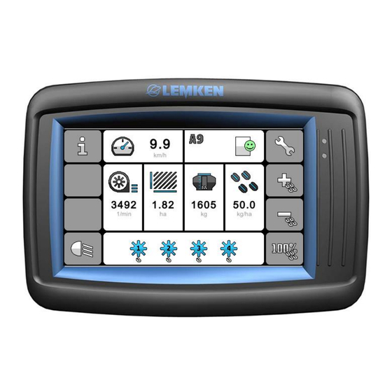
About these operating instructions Operation terminal The following operation terminal can be used for operation of the implement: LET-40 operation terminal Light sensor (1) Multicolour LED (2) Touch screen display (3) CAN connection (4) USB interface (5) On/Off switch (6) 1.3.1 Switch on and off ... -
Page 12: Creating A Screen Shot
About these operating instructions 1.3.2 Creating a screen shot The screenshot of the screen can be sa- ved in PNG format on the USB stick. Insert the USB stick in the operation terminal interface. Depending on the location press the following button for 3 seconds: ... -
Page 13: Symbols Used In The Operating Instructions
Symbols used in the Operating Instructions SYMBOLS USED IN THE OPERATING INSTRUCTIONS Hazard classes The following symbols are used in the Operating Instructions for particularly im- portant information: DANGER Denotes an imminent hazard with high risk, which will result in death or severe physical injury, if not avoided. -
Page 14: Information
Symbols used in the Operating Instructions Information Denotes special user tips and other particularly useful or important information for operation and efficient utilisation. Environmental protection Indication of special recycling and environmental protection measures. Indication of passages The following symbols are used for particular passages in the operating instruc- tions: ... -
Page 15: Safety
Safety SAFETY Switch off the operating terminal DANGER Risk of accidents due to unintentional activation of the operating terminal Unintentional movement of the implement may occur if the operat- ing terminal is switched on. Ensure that the operating terminal is switched off when travel- ling to the field and on public roads. -
Page 16: Layout And Description
Layout and description LAYOUT AND DESCRIPTION Displays and menus Some displays on the operating terminal may differ from those shown in these ope- rating instructions depending on the im- plement type and the equipment installed. This is pointed out if it is relevant to opera- tion of the implement. - Page 17 Layout and description Menu management The following operating elements are available in menu management: (1) Softkey bars for navigation and opera- tion (5) Orientation in text display Selected menu on the implement type Selected menu management Information on page (current page / total number of pages) (6) Displays and functions with colour coding...
-
Page 18: Orientation And Assignment
Layout and description Orientation and assignment Orientation on the implement is aligned in the direction of travel from left to right. 4.2.1 Solitair 23 front tank Metering units Implement with 2 metering units Metering unit 1: on left Metering unit 2: on right Implement with 4 metering units Metering unit 1: on outside left Metering unit 2: on inside left... -
Page 19: Secondary Implement Optidisc 25 Coulter Bar
Layout and description 4.2.2 Secondary implement OptiDisc 25 coulter bar Distributors Distributor 1: outside left Distributor 2: inside left Distributor 3: inside right Distributor 4: outside right Display in the control Section switch The metering units can be switched off in- dividually. -
Page 20: Program Start
Layout and description Program start The start screen appears after the control has been switched on. The system starts up. The operating menu then opens auto- matically. Operating menu The operating menu serves to monitor and control the implement during use. Prior to use implement-specific entries and settings for the control are required. - Page 21 Layout and description Display Contents quick access ● ● ● Current driving speed Settings: [km/h] Driving speed Speed signal Calibration ● ● ● Status of operating sta- Information: tes and messages Error log ● Current track in the Settings: tramline rhythm Tramline mechanism...
- Page 22 Layout and description Display Contents quick access ● Operating mode and Function: position hydraulic Lift and lower harrows. harrows ● ● ● Current hopper filling Settings: weight [kg] Weighing unit Display for the follo- wing equipment: Implement without hydraulic harrow ●...
-
Page 23: Softkeys
Layout and description Display Contents quick access ● ● ● Metering device opera- Settings: tion Sections Status of metering units Status of implement sensor Working position 4.4.2 Softkeys All softkeys of the operating menu are ar- ranged on softkey bars. To navigate through the softkey bars, there are soft- keys with arrows. - Page 24 Layout and description Display Contents Navigation To navigate through the softkey bars, masks and levels, the following softkeys with arrows are available: ● ● ● Scroll to the next softkey bar or mask. ● ● ● Scroll to the previous softkey bar or mask. ●...
- Page 25 Layout and description Display Contents ● ● ● Softkey with 2 functions: Reduce (press softkey) Reset to target (press softkey for 3 seconds) ● ● ● Reset to target. Work lighting To switch the work lighting, the following softkey is available: ●...
-
Page 26: Information
Layout and description Information The information can be used to check and monitor the implement. Open using the softkey Access to the information Different menus can be selected depen- ding on the connected secondary imple- ment:... - Page 27 Layout and description Display Contents ● ● ● «Error log, see page 26» ● ● ● «Counters, see page 27» ● ● ● «Implement configuration, see page 30» ● ● ● «Sensors, see page 33» ● ● ● «Power supply, see page 37» ●...
-
Page 28: Error Log
Layout and description 4.5.1 Error log The present messages are collected in an error log. The messages can be malfunc- tions, warnings or information. Open via menu The colour of the smiley indicates the most serious message. No fault. There may be information (green) ... -
Page 29: Counters
Layout and description Display message: (Only for information and warnings) On Off 4.5.2 Counters Set secondary implement The menu contains different information depending on the connected secondary implement. Precision seed drill Azurit 9 or external implement Opening via the menu Access to the menu administration The menu contains the following counters: ... - Page 30 Layout and description The following displays and functions are available: (Example of job counter) Cultivated area plus area of the tramline [ha] Cultivated area minus area of the tram- line [ha] Distributed quantity [kg] Operating hours of the implement [h] ...
- Page 31 Layout and description Front tank Solitair 23 Opening via the menu Access to the menu administration The menu contains the following counters: Job counter (1/4) Day counter (2/4) Year counter (3/4) Menu: Information | Counter Total counter (4/4) Displays and functions see secondary im- plement: Precision seed drill or external implement.
-
Page 32: Implement Configuration
Layout and description 4.5.3 Implement configuration Set secondary implement The menu contains different information depending on the connected secondary implement. Precision seed drill Azurit 9 or external implement The menu provides an overview of general data and equipment of the implement. Opening via the menu Access to the menu administration Menu: Information | Implement config. - Page 33 Layout and description Coulter bar OptiDisc 25 The menu provides an overview of general data and equipment of the implement. Opening via the menu Selection of implement Front tank Solitair 23 Coulter bar OptiDisc 25 Menu: Information | Implement config. ...
- Page 34 Layout and description Coulter bar OptiDisc 25 Opening implement Access to the menu administration Menu: Information | Implement config. The following displays and functions are available: Implement type Serial number Year of construction Working width [m] Row distance seeding coulters [mm] Pulse wheel Hydraulic pressure setting harrow Coulter pressure...
-
Page 35: Sensors
Layout and description 4.5.4 Sensors Set secondary implement The menu contains different information depending on the connected secondary implement. Precision seed drill Azurit 9 or external implement The menu is used to check the function of individual sensors. Opening via the menu Access to the menu administration The menu contains several pages. - Page 36 Layout and description The following displays and functions are available: Speed signal [km/h] Fan RPM monitoring [rpm] Implement lifting device Pushbutton calibration test Fuses Level indicator Hopper sensor 1: outside left Hopper sensor 2: inside left Hopper sensor 3: inside right ...
- Page 37 Layout and description Coulter bar OptiDisc 25 The menu is used to check the function of individual sensors. Opening via the menu Selection of implement Front tank Solitair 23 Coulter bar OptiDisc 25 Front tank Solitair 23 Opening implement Access to the menu administration Displays and functions see secondary im-...
- Page 38 Layout and description Coulter bar OptiDisc 25 Opening implement Access to the menu administration Functions and states are monitored with sensors. Display via option field: Sensor energised (LED blue) The object has been detected. Sensor energised (LED grey) The object has not been detected.
-
Page 39: Power Supply
Layout and description 4.5.5 Power supply Opening via the menu Access to the menu administration The menu contains several pages. Each control unit is listed on a separate page. Menu: Information | Power supply The following displays and functions are available: Designation of control unit ... -
Page 40: Software Versions
Menu: Information | Software version The following displays and functions are available: Designation of control unit Job computer Operation terminal Metering motor System version Hardware Operating system LEMKEN operating system Internal storage Application... -
Page 41: Metering Motors
Layout and description 4.5.7 Metering motors Opening via the menu Access to the menu administration Each metering motor is listed on a separa- te page. Menu: Information | Metering motors The following displays and functions are available: Voltage [V] ... -
Page 42: Seed Pipe Monitoring
Layout and description 4.5.8 Seed pipe monitoring Seed pipe monitoring detects disturbances in the seed flow using sensors and it moni- tors the following function states of the im- plement: Metering units Tramlines Opening via the menu Access to the menu administration Menu: Information | Seed pipe monitoring The following displays and functions are available:... - Page 43 Layout and description Information sensors Distributor 1 Distributor 2 Distributor 3 Distributor 4 Status: Everything ok (green) Error (red) Manual restart: Communication seed flow monitoring (Kfü)
- Page 44 Layout and description Information sensors Open via button Access to the information Depending on the number of shares in a tramline, the sensors are divided specific to the task. (See Settings tramline mecha- nism) Assignment, switching and activity of the sensors are identified for each distributor by colour and symbol: ...
- Page 45 Layout and description Comparison between sensors on the implement On one distributor the lines of the sensors are connected in series. First, the sensors of the tramlines are connected in series. This is followed by the sensors of the seed pipes.
-
Page 46: Settings
Layout and description Settings The settings can be used to set up the im- plement specifically for each use. Open using the softkey Access to the settings Different menus can be selected depen- ding on the connected secondary imple- ment: Display Contents ●... - Page 47 Layout and description Display Contents ● ● ● «Secondary implement, see page 55» ● «Working position, see page 58» ● ● ● «Weighing unit, see page 59» ● «Intermitted tramline mechanism, see page 60» ● «Coulter pressure, see page 61» ●...
-
Page 48: Calibration
Layout and description 4.6.1 Calibration The menu can be selected in the following operating state: Speed of the fan below 500 rpm Implement has been lifted The calibration test is used to calibrate the distribution for the implement: Program sequence Before running the calibration test, enter the following basic parameters:... -
Page 49: Tramline Mechanism
Layout and description Opening via the menu Access to the menu administration Menu: Settings | Calibration The following displays and functions are available: Type of distribution Weight of the distribution [kg/ha] Minimum operating speed [km/h] Maximum operating speed [km/h] ... - Page 50 Layout and description The following displays and functions are available: Tramline mechanism: on/off Working width care device [m] Tramline cycle For even tramline rhythm: Creating the tramline: 1 pass / 2 passes When creating the tramline in two passes: ...
-
Page 51: Distribution Rate
Layout and description 4.6.3 Distribution rate Opening via the menu Access to the menu administration Menu: Settings | Distribution rate The following displays and functions are available: Current distribution rate [kg/ha] Computer Operating speed minimum/maximum [km/h] Increment distribution rate [%] ... -
Page 52: Monitoring: Fan
Layout and description 4.6.4 Monitoring: fan Opening via the menu Access to the menu administration Menu: Settings | Monitoring: fan The following displays and functions are available: Minimum fan speed [rpm] Maximum fan speed [rpm] Alarm function on/off... -
Page 53: Monitoring
Layout and description 4.6.5 Monitoring If a sensor is defective, the alarm function can be deactivated. Whenever the electronic control is swit- ched on, all alarm functions are activated. Previously deactivated alarm functions are automatically activated after a restart. Set secondary implement The menu contains different settings de- pending on the connected secondary im- plement. - Page 54 Layout and description Coulter bar OptiDisc 25 Opening via the menu Access to the menu administration Menu: Settings | Monitoring The following displays and functions are available: Fan RPM monitoring Hopper level indicator Seed pipe monitoring Distributor monitoring...
-
Page 55: Driving Speed
Layout and description 4.6.6 Driving speed The driving speed is evaluated for the dis- tribution rate. For this reason the system requires a precise speed signal. To determine the driving speed, the follo- wing speed signals are available: Radar Signal secondary implement: ... - Page 56 Layout and description Radar / signal secondary implement Access to the menu administration Menu: Settings | Driving speed The following displays and functions are available: Select speed signal to determine the dri- ving speed Current operating speed [km/h] ...
-
Page 57: Remaining Quantity Discharge
Layout and description 4.6.7 Remaining quantity discharge The switch to the menu can be made in the following operating states: Fan speed below 500 rpm or implement has been lifted. Opening via the menu Access to the menu administration Menu: Settings | Rem. - Page 58 Layout and description No secondary implement Access to the menu administration Menu: Settings | Sec. implement The following displays and functions are available: Select secondary implement. Automatic search function Coulter bar OptiDisc 25 Access to the menu administration Menu: Settings | Sec.
- Page 59 Layout and description Precision seed drill Azurit 9 Access to the menu administration Menu: Settings | Sec. implement The following displays and functions are available: Select secondary implement. Implement width Messages Number of metering devices Automatic section switch front mounted implement ...
-
Page 60: Working Position
Layout and description External implement Access to the menu administration Menu: Settings | Sec. implement The following displays and functions are available: Selection of secondary implement Implement width Number of used metering motors front tank Automatic search function 4.6.9 Working position Open via menu Access to the menu management... -
Page 61: Weighing Unit
Layout and description 4.6.10 Weighing unit Opening via the menu Access to the menu administration Menu: Settings | Weighing unit The following displays and functions are available: Gross weight hopper content [kg] Hopper refilled with content [kg] / distri- buted rate ... -
Page 62: Intermitted Tramline Mechanism
Layout and description 4.6.11 Intermitted tramline mechanism To subsequently reduce soil erosion on slopes, the tramline is alternately interrup- ted and created. Opening via the menu Access to the menu administration Menu: Settings | Intermitted tramline mechanism The following displays and functions are available: ... -
Page 63: Coulter Pressure
Layout and description 4.6.12 Coulter pressure Opening via the menu Access to the menu administration Menu: Settings | Coulter pressure The following displays and functions are available: Increase coulter pressure. Reduce coulter pressure. -
Page 64: Operation Terminal
4.6.13 Operation terminal Open via menu Access to the menu management Menu: Settings | Operation terminal The following displays and functions are available: Switch sound on and off Set screen brightness 4.6.14 Service Access for LEMKEN Service only. -
Page 65: Driving On Public Roads
Driving on public roads DRIVING ON PUBLIC ROADS Switch the operating terminal off before travelling on the road DANGER The implement may move accidentally if the operating terminal is switched on. This can cause serious accidents. Ensure that the operating terminal is switched off during road travel. -
Page 66: Preparations Prior To Operation
Preparations prior to operation PREPARATIONS PRIOR TO OPERATION Setting secondary implement The status field in the operating menu pro- vides information about the currently set secondary implement. No secondary implement Coulter bar OptiDisc 25 Precision seed drill Azurit 9 ... - Page 67 Preparations prior to operation The mounted secondary implement is dis- played. If no secondary implement is found: Secondary implement not found. The display appears: No secondary implement If no secondary implement has been se- lected, a message appears. Confirm message. ...
-
Page 68: Manually Selecting Secondary Implement
Preparations prior to operation 6.1.2 Manually selecting secondary implement The current secondary implement is dis- played. Select assigned input field. The selection dialogue appears: No secondary implement Coulter bar Azurit 9 External implement Select required function. ... -
Page 69: Setting Up Secondary Implement
Preparations prior to operation 6.1.3 Setting up secondary implement Coulter bar OptiDisc 25 In menu administration Menu: Settings | Sec. implement The following displays and functions are available: The secondary implement has been selec- ted. No other settings are required. Precision seed drill Azurit 9 In menu administration Menu: Settings | Sec. - Page 70 Preparations prior to operation External implement In menu administration Menu: Settings | Sec. implement The secondary implement has been selec- ted. Other settings are required: Enter implement width. Select number of the metering motors to be used. The calibration test runs on the basis of the selected motors.
-
Page 71: Setting Up Sensor Source Of The Working Position
Preparations prior to operation 6.1.4 Setting up sensor source of the working position Precision seed drill Azurit 9 The following sensor sources can be sel- ected: Lifting device front power lift. Lifting device precision seed drill Azu- rit 9. ... -
Page 72: Reset Counters
Preparations prior to operation Reset counters Call up menu. Alternative: Quick access directly to the operating menu In menu management Menu: Information | Hectare counter Scroll to desired counter. Press the button for 2 seconds. The counter is reset to zero. -
Page 73: Calibrating Weighing Unit
Preparations prior to operation Calibrating weighing unit Before using for the first time: Calibrate weighing unit. 6.3.1 Weighing correctly The weighing unit determines incorrect values in the following states: Weighing unit not calibrated Implement moving Implement not aligned horizontally The precision of the weighing unit is +5…- To obtain this precision: ... -
Page 74: Implement Without Pressure System
Preparations prior to operation 6.3.2 Implement without pressure system Preparation Empty hopper. Park tractor and implement on level ground. Align implement level with the ground. (Measure distance of the supports) Open menu. In menu administration Menu: Settings | Weighing unit Calibration ... -
Page 75: Implement With Pressure System
Preparations prior to operation 6.3.3 Implement with pressure system The weighing unit determines different va- lues depending on the state of the imple- ment. Generated pressure in the hopper will result in a difference. Use of the counters: Counter 1: Displays the weight during operation with pressure system. - Page 76 Preparations prior to operation Calibration under pressure Counter 1 Close cover. Switch on fan at the required speed. The counter displays, if required, a positive or negative value. Reset counters. The counter of the weighing unit has be- en calibrated.
-
Page 77: Use Weighting Unit
Preparations prior to operation Use weighting unit Call up menu. In menu management Menu: Settings | Weighing unit 6.4.1 Reset weighing unit counter Filled tank contents Counting is based on weighing of the filled amount. The gross weight of the tank is displayed. (in kg) The refilled amount is added. -
Page 78: Setting Up Monitoring Of The Fan
Preparations prior to operation Range The range is the theoretically calculated possible remaining area available with the current distribution rate and tank contents. Setting up monitoring of the fan Open menu. Alternative: Quick access directly from the operating menu In menu administration Menu: Settings | Monitoring: fan Changing maximum fan speed... - Page 79 Preparations prior to operation Changing minimum fan speed If the fan speed falls below the minimum, a message appears. Select assigned input field. The input dialogue appears. Enter required value. (Unit of measure- ment 0…9999 rpm) Confirm input. The value has been accepted.
-
Page 80: Using Tramline Mechanism
Preparations prior to operation Using tramline mechanism The tramline rhythm is automatically spe- cified on the basis of the following parame- ters: Set working width of the care device Working width of the seed drill Specification of the tramline type ... -
Page 81: Switching Tramline Mechanism On And Off
Preparations prior to operation 6.6.1 Switching tramline mechanism on and off Select assigned switch. On Off Menu administration switched off. 6.6.2 Creating tramlines specific to the order The tramlines can be created in one or two passes. (Not possible for all rhythms) Possible tramline rhythms: ... - Page 82 Preparations prior to operation Changing working width of the care device The entered working width of the care de- vice must be rounded up to 1 metre. When the working width has been entered, the tramline rhythm is automatically calculated. ...
- Page 83 Preparations prior to operation 1. Creating tramline in one pass The first pass must occur with half imple- ment width. After leaving the menu: A note appears. The first pass must be sown with half im- plement width. Confirm note. ...
- Page 84 Preparations prior to operation 2. Creating tramline in two passes Prerequisite The implement must be equipped with a tramline mechanism 4x2, 4x3 or 4x4 tram- lines. Location of the field edge If the location of the field edge is relevant for the tramline rhythm, this display ap- pears.
-
Page 85: Distributor Configuration
Preparations prior to operation 6.6.3 Distributor configuration The distributor configuration affects the metering speed when tramline is switched on. The speed is adjusted automatically. Open menu administration page 2. Depending on the number of shares in a tramline, corresponding tasks are assigned to the sensors. - Page 86 Preparations prior to operation In the operating menu Current function: Off On Interruption Example 1: calculated tramline rhythm 4.00 (Tramline is created in one pass) Display in the settings: Type of pass: (1) Location of the field edge (2) ...
-
Page 87: Setting Up Intermitted Tramline Mechanism
Preparations prior to operation Example 2: calculated tramline rhythm 4.00R (Tramline is created in two passes) Display in the settings: Type of pass: (1) Location of the field edge (2) Tramline rhythm (3) Menu: Settings | Tramline mechanism 1. - Page 88 Preparations prior to operation Switching function on and off Select assigned switch. On Off Entering distance of tramline monitoring The tramline is interrupted for the set dis- tance. Select assigned input field. The input dialogue appears. ...
- Page 89 Preparations prior to operation In the operating menu Current function: Off On Example: calculated tramline rhythm 4.00 L (Tramline is created in two passes) Display in the settings: Type of pass: (1) Location of the field edge (2) ...
-
Page 90: Setting Monitoring Of The Driving Speed
Preparations prior to operation Setting monitoring of the driving speed Open menu. Alternative: Quick access directly from the operating menu In menu administration Menu: Settings | Driving speed 6.7.1 Changing speed signal The current speed signal is displayed. Speed signal on implement side: ... -
Page 91: Setting Up Speed Signal On The Implement Side
Preparations prior to operation 6.7.2 Setting up speed signal on the implement side Select speed signal: Radar In menu administration 100 m calibration 6.7.3 Setting up speed signal secondary implement Select speed signal: In menu administration... -
Page 92: Setting Up Simulated Driving Speed
Preparations prior to operation 6.7.4 Setting up simulated driving speed Select speed signal: Simulated speed In menu administration Select associated input field. The input dialogue appears. Enter value. (0.0…100.0 km/h) Confirm input. The value has been changed. In the operating menu: Current driving speed with additional iden- tification of the selected function... -
Page 93: Starting The Calibration Test
Preparations prior to operation 6.8.1 Starting the calibration test After starting: The calibration test must run without any errors. If the calibration test is terminated, distribution will not be precise. Select button. The calibration settings open. The following inputs are required: ... -
Page 94: Setting Distribution And Specific Weight
Preparations prior to operation 6.8.2 Setting distribution and specific weight Selectable distributions Distribution Fixed value [g/l] Beans Spelt Fertiliser Peas Barley Grass Oats Clover Rape Sunflowers Triticale Wheat... - Page 95 Preparations prior to operation Select assigned selection field. The selection dialogue appears. Select distribution. Confirm input. The selection has been accepted. When the distribution has been selected, the specific weight is queried. The following displays and functions are available: ...
- Page 96 Preparations prior to operation Determine weight by weighing [g/l] Select assigned option field. The function for entering the exact litre weight is active. Provide measuring cup (volume 1 l). Determine tare weight of the measuring cup. Fill the measuring cup with exactly 1 l of distribution.
-
Page 97: Setting Target Distribution Rate
Preparations prior to operation 6.8.3 Setting target distribution rate The distribution rate is required in the unit of measurement kg/ha. If the distribution rate is in seeds per m², the dependent distribution rate can be converted to kg per ha. See «Converting distribution rate (seeds/m²... -
Page 98: Converting Distribution Rate (Seeds/M² > Kg/Ha)
Preparations prior to operation 6.8.4 Converting distribution rate (seeds/m² > kg/ha) Select button. The converter opens. Menu: Settings | Calibration | Converter The following values are required for the conversion: Required distribution rate [1/m Thousand grain weight [g] ... - Page 99 Preparations prior to operation Entering thousand grain weight The thousand grain weight is the weight of 1000 seeds. Select assigned input field. The input dialogue appears. Enter value. (Unit of measurement 0.1…999.9 g) Confirm input. Entering germination capacity The germination capacity specifies the quality of the seeds as a percentage which form a seedling.
-
Page 100: Setting The Driving Speed
Preparations prior to operation 6.8.5 Setting the driving speed The chamber size is optimised for the set driving speed. To set the required mean driving speed: Select assigned input field. The input dialogue appears. Enter value. (Unit of measurement 0…20 km/h) ... -
Page 101: Setting Metering
The parameters entered beforehand are used to determine a recommended setting of the metering wheels, if available. A user-specific setting is also possible. LEMKEN recommendation LEMKEN recommendation not available (grey) User-specific setting... -
Page 102: Selection Of Fertiliser
Preparations prior to operation 6.9.1 Selection of fertiliser User-specific setting (LEMKEN recommendation not available) Different metering wheel sets can be used to distribute fertiliser. Selecting metering wheel set Select mounted metering wheel set: Seeds metering wheel set Universal metering wheel set ... -
Page 103: Selection Of Seeds
Preparations prior to operation 6.9.2 Selection of seeds LEMKEN recommendation Select LEMKEN recommendation. The metering wheels are set on the basis of the entered distribution. Metering wheel is to be used Metering wheel is not to be used ... - Page 104 Switch required metering wheels on or off. Metering wheel is not to be used Metering wheel is to be used User-specific setting (LEMKEN recommendation not available) Set metering wheels specific to the user: The metering wheels were switched off be- forehand.
-
Page 105: Filling The Metering Wheels
Preparations prior to operation 6.9.3 Filling the metering wheels Select softkey. Screen text Ensure that the cellular wheels have been correctly set. Rotate metering device in the next step Select softkey. Screen text Wait until all metering devices have been filled. -
Page 106: Starting The Calibration Test
Preparations prior to operation 6.9.4 Starting the calibration test Duration and calibration speed have been calculated for the corresponding distributi- on. The calibration time has been specially synchronised with the distribution. The metering devices can be stopped at any time during the calibration time and the calibration test ended. - Page 107 Preparations prior to operation Starting and stopping the metering device Starting the metering device: Select softkey. Stop the metering device during the calib- ration time: Select softkey. Alternative: Operation via push switch Prerequisite The function is possible as soon as the pushbutton is lit red.
-
Page 108: Entering The Weight
Preparations prior to operation 6.9.5 Entering the weight Enter determined gross weight of all me- tering units. The counted motor impulses and the weight are used to determine the calibrati- on value [g/imp]. Select softkey. The input of the gross weight is transferred to the following page and vice versa. -
Page 109: Ending The Program
Preparations prior to operation 6.9.7 Ending the program Screen text Close metering flaps again. Select softkey. The program is completed. 6.9.8 Result for calibrated distribution The result is retained when the electronic control is switched off. It is not necessary to recalibrate. The result is displayed with the following set values: ... -
Page 110: Setting Distribution Rate
Preparations prior to operation Confirm result Select the softkey. The calibration test has been performed. Back to operating menu. Repeat calibration test Select the softkey. Back to parameter settings. 6.10 Setting distribution rate Open menu. Alternative: Quick access directly from the operating menu In menu administration Menu: Settings | Distribution rate... -
Page 111: Changing Distribution Rate
Preparations prior to operation 6.10.1 Changing distribution rate If a complete calibration has been run be- forehand, the distribution rate can be changed separately. A recalibration is not required. Select assigned input field. The input dialogue appears. Enter required distribution rate. (Unit of measurement 1.0…400.0 kg/ha) ... - Page 112 Preparations prior to operation Metering supply activated Metering starts as soon as the following conditions have been satisfied: Fan speed at least 500 rpm or RPM mo- nitoring deactivated Coulter bar has been lowered. The metering speed matches the entered driving speed.
-
Page 113: Manually Switching The Track
Preparations prior to operation 6.11 Manually switching the track Whenever the coulter bar is lifted, the track is automatically shifted. To prevent automatic shifting when lifting the coulter bar in a track, the tramline me- chanism can be stopped. Track backwards ... -
Page 114: Communication With Azurit 9
Preparations prior to operation 6.12 Communication with Azurit 9 Establishing a connection Settings on the CCI operation terminal Azurit 9: Select front tank. (see operating instructions for MegaSeed control) Connection of Azurit 9 to front tank The following operating elements are in- tegrated in the CCI operation terminal of the Azurit: ... -
Page 115: Operation
Operation OPERATION Set operation terminal, sound and brightness Call up menu. In menu management Menu: Settings | Operation terminal Sound Select function. Sound on Sound off Brightness Select assigned input field. The input dialog appears. ... -
Page 116: Checking The Status
Operation Checking the status The display contains information about cur- rent messages and operating states of the implement in conjunction with the control. 7.2.1 Messages The messages are differentiated according to severity level: Everything is correct (no messages) Possible operating error (there is a mes- sage) ... -
Page 117: Monitor Speed Signal
Operation Monitor speed signal The display contains information on the current settings for the speed signal. Speed signal is active. Simulated speed is active. Procedure for messages 7.4.1 Display and remedy messages If a message appears: Confirm message. The present message is collected in an er- ror log. - Page 118 The message displayed provides informa- tion on: Fault description Possible cause Corrective measure See "Diagnostic list, page 136". Remedy the error. The message disappears. Everything OK, no messages. If the message cannot be remedied: Please contact LEMKEN Service.
-
Page 119: Hide Messages Prematurely
Operation 7.4.2 Hide messages prematurely Warnings and malfunctions reappear every 20 seconds after confirmation until the message is remedied. Information is only shown repeatedly if certain conditions are met. (E.g., device excavated) Messages relating to information and warnings which cannot be remedied im- mediately can be hidden. -
Page 120: Activating And Deactivating Alarm Functions
Operation Activating and deactivating alarm functions All alarm functions are active following a restart. Precision seed drill Azurit 9 / external implement Open menu. In menu administration Menu: Settings | Monitoring The current function is displayed. To switch the function: ... - Page 121 Operation Hopper level The following messages are associated with this setting option: L4606 Level too low The status display in the operating menu provides information about the deactivated setting option. Alarm function off If the alarm function is deactivated with this message, the smiley is green again.
- Page 122 Operation Fan RPM monitoring The following messages are associated with this setting option: L4307 Fan speed too low L4308 Fan speed too high The status display in the operating menu provides information about the deactivated setting option. Alarm function off Hopper level The following messages are associated with this setting option:...
- Page 123 Operation Seed pipe monitoring The following messages are associated with this setting option: L4306 Malfunction seed flow L4312 No seed L4334 Supply voltage too low L4335 Too few sensors L4338 Sensor invalid L4339 Seed pipe blocked L4340 ...
-
Page 124: Switching On Work Lighting
Operation Switching on work lighting In order to use the implement in the dark, working lights including hopper lights are provided. To switch the working lights on and off: Select the softkey. The status field provides information on the switched on function. -
Page 125: Switch The Metering Units On And Off
Operation 7.7.2 Switch the metering units on and off Call up menu: Select display. In menu management Menu: Settings | Width sections Single metering units To switch each metering unit off or on sep- arately: Select button. On ... -
Page 126: Control Distribution Manually
Operation 7.7.3 Control distribution manually The fan must be activated for manual operation of the metering device. To avoid seed gaps or overlapping, the metering units can be started and stopped manually. Prerequisite Fan speed at least 500 rpm or fan speed monitoring deactivated Manual start ... -
Page 127: Changing Distribution Rate
Operation Manual stop To switch off the manual function prematu- rely. Select the softkey. The metering units are stopped. Press the softkey for 3 seconds. The metering units are deactivated 7.7.4 Changing distribution rate The distribution rate can be increased or reduced at the set increment. -
Page 128: Lifting And Lowering Harrow
Operation Lifting and lowering harrow The harrow can be automatically or manu- ally actuated. To switch the function: Select display area 3 seconds. Automatic mode When activated, the harrow is automatical- ly adjusted to the position of the coulter bar. -
Page 129: Manual Mode
Operation 7.8.2 Manual mode The harrow is not lifted and lowered to- gether with the implement. The harrow is actuated only manually. A symbol shows the current position of the harrow: Lowered Lifted To manually lift and lower the harrow dur- ing the pass: ... -
Page 130: Cleaning And Care
Cleaning and care CLEANING AND CARE Discharging remaining quantity When the remaining quantity has been discharged, a new calibra- tion test is required. Open menu. In menu administration Screen text When remaining quantity discharge has been activated, a new calibration test is required. -
Page 131: Start Program
Cleaning and care 8.1.1 Start program Select softkey. Screen text Setting positions are being searched for … Screen text All set positions have been found. Screen text Ensure that all seed wheels have been connected to guarantee quick discharge. Rotate metering device in the next step. -
Page 132: Starting Discharge
Cleaning and care 8.1.2 Starting discharge Select softkey. Screen text Remaining quantity discharge is running. Stop process via the terminal or the push- button. Stop program: Select softkey. Screen text Start remaining quantity discharge by pressing the Play button or the pushbutton. End process by pressing on the chequered flag. - Page 133 Cleaning and care Starting and stopping the metering device Starting the metering device: Select softkey. To discharge the full collectors, the dis- charge can be interrupted at any time. Stop metering devices: Select softkey. Alternative: Operation via push switch Prerequisite The function is possible as soon as the pushbutton is lit red.
-
Page 134: Ending Discharge
Cleaning and care 8.1.3 Ending discharge Discharge can be ended: When the set discharge time has elap- After an interruption Select softkey. Screen text Close metering flaps again. Back to the operating menu: Select softkey. -
Page 135: Configuration And Calibration
Configuration and calibration CONFIGURATION AND CALIBRATION Pulse wheel and radar calibration value The calibration value of the pulse wheel and radar can be entered manually or de- termined over a set distance. 9.1.1 Enter the calibration value Select button. The program opens. - Page 136 Configuration and calibration Call up the program Select button. The program opens. Drive up to the start mark. Lower the coulter bar. To start calibration: Select the softkey. Drive off. Stop at the end mark. To end calibration: ...
-
Page 137: Troubleshooting
Troubleshooting TROUBLESHOOTING 10.1 Messages A current message is shown on the touch screen. The code provides details on the current fault which is described in the di- agnostic list. The messages are coloured according to their severity. Malfunctions (Red colour code) Example shown: ... -
Page 138: Diagnostic List
Troubleshooting 10.2 Diagnostic list 10.2.1 Malfunctions Malfunctions Cause Measure L4001 Malfunction in the electro- nics of the metering motor Hardware metering motor Motor not connected L4002 Motor defective No CAN communication with metering motor Cable form defective ... -
Page 139: Warnings
Troubleshooting 10.2.2 Warnings Warnings Cause Measure L4303 Last calibration test has not been completed. Me- Calibration test incomple- tering chamber may have been incorrectly calibra- ted. Drive faster. L4304 The current driving speed is less than the calculated Run Operating speed fallen calibration minimum driving speed of... - Page 140 Troubleshooting Warnings Cause Measure L4309 The currently entered working width of the care Tramline rhythm not device cannot be imple- available mented with the equipment of the imple- ment. L4311 Operating pressure for switching the tramlines Tramline does not switch too low L4312 The sensor is not detec-...
- Page 141 Troubleshooting Warnings Cause Measure L4329 The metering (lowest set- ting of the metering Calibration of metering chamber) cannot be device: Hard stop not calibrated. possible Reason: Metering jammed. … L4330 The drive torque on the Check metering for for- metering motor is too Drive torque of the mete- eign objects.
- Page 142 Troubleshooting Warnings Cause Measure Check voltages on the L4334 The LJR module signals LMC-X that its supply voltage has Seed pipe monitoring: (LPB1) Powerbox. been below 8 V for Supply voltage of the mo- 5 seconds. Check plug connections dule for seed pipe monito- ring (LJR) too low ...
- Page 143 Troubleshooting Warnings Cause Measure L4339 Too many seeds are de- Contact LEMKEN Ser- tected. Seed pipe monitoring: vice. Excess quantity Check settings of the L4340 The degree of soiling is distribution. above the permitted value Seed pipe monitoring: for the distribution just se- ...
- Page 144 Troubleshooting Warnings Cause Measure L4358 Position of locking motor unknown L4360 Cable break weighing cell L4400 Software versions of job computer and operation terminal incompatible L4401 No CAN connection to the secondary implement L4402 Combination of primary implement and secondary implement incompatible L4403 Software version of the...
-
Page 145: Notes
Troubleshooting 10.2.3 Notes Notes Cause Measure L4600 At least one sensor de- tects an empty state. Fill level sensor hopper at bottom (metering device) signals empty hopper. L4603 In the tramline rhythm start with a half implement Start with half implement width. -
Page 146: Fuses
The electronic control is protected from overload by various fuses. 10.3.1 Position of the fuses Battery installation kit Strip fuse 60 amps (1) LEMKEN Powerbox (LPB1) Blade fuses 4x15 amps (1) Voltage of metering units 1x10 amps (2) Lighting ... -
Page 147: Changing Fuses
Replace fuse strip with a new fuse strip which has the same amperage. Close fuse holder. Connect electronic control to the battery. LEMKEN Powerbox (LPB1) Visual inspection The function of the blade fuses is con- firmed by a control LED. - Page 148 Troubleshooting LED display 1 ECU_POWER LED on (green): Voltage is applied LED on (red): Voltage is applied, but the polarity is reversed 2 Power supply of motors LED on: Relay is switched on 3 Work lighting LED on: Relay is switched on 4 ECU_POWER LED on: Voltage is applied 5 POWER fuse...
-
Page 149: Annex
Annex ANNEX 11.1 Tramline system Tramline rows and track widths can be flexibly adapted to the tramline system. Number of closed tramline rows for symmetrical and asymmetrical rhythms: Symmetrical Asymmetrical Seeding coulter Tramline width rhythm rhythm row spacing [mm] [mm] 11.2 Overview of tramline rhythm This overview shows all the tramline rhythms available with the electronic control... - Page 150 Annex Tramline mechanism: 2x2, 2x3 and 2x4 rows 3.00 3.50 4.00 4.50 5.00 6.00 8.00 9.00 10.00 12.00 1.00 1.00 1.00 1.00 2.00 1.00 2.00 2.00 1.00 3.00 2.00 1.00 10.0 2.00 1.00 10.5 3.00 11.0 12.0 4.00 3.00 2.00 1.00 13.0 13.5...
- Page 151 Annex 3.00 3.50 4.00 4.50 5.00 6.00 8.00 9.00 10.00 12.00 32.0 8.00 4.00 33.0 11.00 34.0 35.0 10.0 7.00 36.0 12.00 9.00 8.00 6.00 4.00 3.00 37.0 38.0 39.0 13.00 40.0 10.00 8.00 5.00 4.00 40.5 9.00 41.0 42.0 14.00 12.00 7.00...
- Page 152 Annex Tramline mechanism: 4x2, 4x3 and 4x4 rows 3.00 3.50 4.00 4.50 5.00 6.00 8.00 9.00 10.00 12.00 1.00 1.00 1.50 1.00 1.00 2.00 1.50 1.00 2.33 2.00 2.66 2.00 1.00 3.00 2.00 1.50 1.00 10.0 3.33 2.50 2.00 1.00 10.5 3.50 3.00...
- Page 153 Annex 3.00 3.50 4.00 4.50 5.00 6.00 8.00 9.00 10.00 12.00 32.0 8.00 5.33 4.00 2.66 33.0 11.00 5.50 34.0 35.0 10.0 7.00 36.0 12.00 9.00 8.00 6.00 4.50 4.00 3.00 37.0 38.0 39.0 13.00 6.50 40.0 10.00 8.00 6.66 5.00 4.00 3.33...
-
Page 154: Uneven, Whole-Number Rhythm
Annex 11.2.1 Uneven, whole-number rhythm Implement Crop protection implement... -
Page 155: Even, Whole-Number Rhythm
Annex 11.2.2 Even, whole-number rhythm... -
Page 156: Even, Whole-Number Rhythm, In Two Passes
Annex 11.2.3 Even, whole-number rhythm, in two passes Pass starts on the left side of the field:... - Page 157 Annex Pass starts on the right side of the field:...
-
Page 158: Half Rhythm
Annex 11.2.4 Half rhythm Pass starts on the left side of the field:... - Page 159 Annex Pass starts on the right side of the field:...
-
Page 160: One-Third Rhythm
Annex 11.2.5 One-third rhythm Pass starts on the left side of the field:... - Page 161 Annex Pass starts on the right side of the field:...
-
Page 162: Index
Index INDEX Calibration ...................... 51, 99 CALIBRATION ....................145 CONFIGURATION....................145 Coulter pressure ....................67 Counters ....................... 30 Diagnostic list ..................... 149 Displays with quick access ................... 21 Distribution rate ..................54, 118, 137 Driving speed ......................58 Error log ........................ 29 Fuses ........................ - Page 163 Index ROADdriving ......................69 Secondary implement ..................60, 71 Seed pipe monitoring .................... 44 Sensors ........................ 37 Service ........................68 Settings ......................... 49 Softkeys ........................ 24 Software versions ....................42 Speed signal ......................97 Switch off the working light ................... 69 Switching on work lighting ..................
Need help?
Do you have a question about the FieldTronic EcoDrill Solitair 23 and is the answer not in the manual?
Questions and answers