Table of Contents
Advertisement
Quick Links
Operating & Installation Instructions
Translation of the Original Assembly Instructions EN
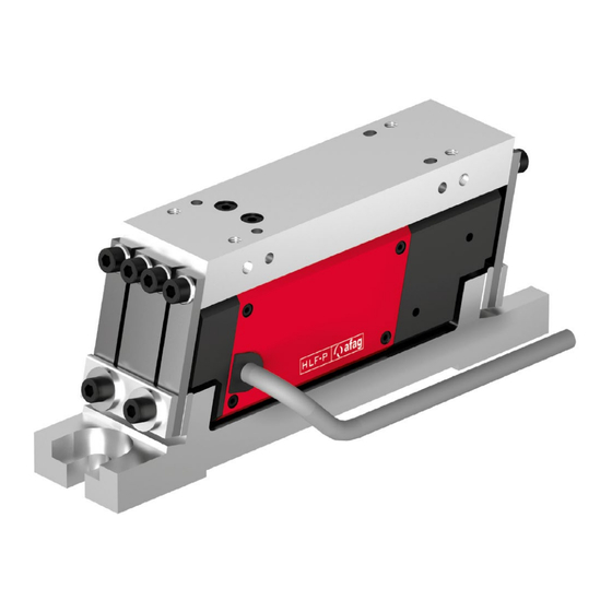
Linear feeder HLF07-P (230 V/50 Hz)
Linear feeder HLF12-P (230 V/50 Hz)
Operating & Installation Instructions EN
Linear Feeder
HLF07-P / 12-P
HLF-07- P / HLF12-P
Order no.: 50260509
Order no.: 50259973
Date 23.08.2023
Version 4.0
1–44
Advertisement
Table of Contents

Related Manuals for Afag HLF07-P


Summary of Contents for Afag HLF07-P
- Page 1 Operating & Installation Instructions Linear Feeder HLF07-P / 12-P Translation of the Original Assembly Instructions EN Linear feeder HLF07-P (230 V/50 Hz) Order no.: 50260509 Linear feeder HLF12-P (230 V/50 Hz) Order no.: 50259973 Operating & Installation Instructions EN HLF-07- P / HLF12-P Date 23.08.2023...
- Page 2 Your Afag team © Subject to modifications The linear feeders have been designed by Afag Automation AG according to the state of the art. Due to the constant technical development and improvement of our products, we reserve the right to make technical changes at any time.
-
Page 3: Table Of Contents
Table of contents Table of contents General ........................5 Contents and purpose of this manual ............5 Explanation of symbols................. 5 Additional symbols ..................6 Warranty ....................... 7 Liability ......................7 Safety instructions ....................8 General ......................8 Intended use ....................8 Foreseeable misuse .................. - Page 4 Wear parts, repairs ..................39 Decommissioning and disposal ................. 40 10.1 Safety instructions ..................40 10.2 Decommissioning ..................40 10.3 Disposal ...................... 40 4 – 44 Operating & Installation Instructions EN HLF07-P / HLF12-P Date 23.08.2023 Version 4.0 ...
-
Page 5: General
General General Contents and purpose of this manual These operating and installation instructions contain important information on assembly, commissioning, functioning and maintenance of the linear feeder HLF to ensure safe and efficient handling and operation. Consistent compliance with these operating instructions will ensure: ... -
Page 6: Additional Symbols
In these assembly instructions the following symbols are used to highlight instructions, results, references, etc.. Symbol Description Instructions (steps ...) Results of actions References to sections Enumerations not ordered 6 – 44 Operating & Installation Instructions EN HLF07-P / HLF12-P Date 23.08.2023 Version 4.0 ... -
Page 7: Warranty
This does also apply to defective accessories and wear parts. Normal wear and tear are excluded from the warranty. The warranty covers the replacement or repair of defective Afag parts. Further claims are excluded. The warranty shall expire in the following cases: ... -
Page 8: Safety Instructions
observance of all instructions given in this manual. compliance with the inspection and maintenance work and the specifications in the data sheets, using only original spare parts. 8 – 44 Operating & Installation Instructions EN HLF07-P / HLF12-P Date 23.08.2023 Version 4.0 ... -
Page 9: Foreseeable Misuse
Safety instructions Foreseeable misuse Any use other than or beyond the intended use described above is considered a misuse of the linear feeder. WARNING Risk of injury if the HLF is not used for its intended purpose or if it is foreseeable used incorrectly! The improper use of the HLF poses a potential hazard to the personnel. -
Page 10: Obligations Of The Personnel
Authorized persons who due to their specialized professional training, expertise and experience can identify risks and preventing possible hazards arising from the use of the machine. 10 – 44 Operating & Installation Instructions EN HLF07-P / HLF12-P Date 23.08.2023 Version 4.0 ... -
Page 11: Personal Protective Equipment (Ppe)
Changes & Modifications No changes may be made to the linear feeders which have not been described in these operating instructions or approved in writing Afag Automation AG. Excluded from this are the rails stated in chap. 6.4.1 and chap. -
Page 12: Danger Due To Electricity
Danger due to alternating magnetic fields! The alternating magnetic fields occurring in the immediate vicinity of the HLF07-P/ HLF12-P can affect the proper functioning of e.g. pacemakers and defibrillators. Persons with a pacemaker must keep a safety distance of at least 10 cm. -
Page 13: Mechanical Hazards
Safety instructions 2.8.4 Mechanical hazards CAUTION Danger of injury by moving components! Limbs can be crushed by moving components! Work on and with the HLF may only be carried out by qualified personnel. Never reach into the system during normal operation! Operating &... -
Page 14: Technical Data
Technical data Technical data Dimensional drawing HLF-P Fig. 1 Dimensional drawing HLF-P 14 – 44 Operating & Installation Instructions EN HLF07-P / HLF12-P Date 23.08.2023 Version 4.0 ... -
Page 15: 3.2 Technical Data Hlf-P
Technical data 3.2 Technical data HLF-P Operating & Installation Instructions EN HLF-07- P / HLF12-P Date 23.08.2023 Version 4.0 15–44 ... -
Page 16: Accessories
Soft start/soft stop PSG1 230V, ±10%, 50/60 Hz 50211833 For more information on the controller, see chap. 6.3 and the controller manufacturer's instructions. 16 – 44 Operating & Installation Instructions EN HLF07-P / HLF12-P Date 23.08.2023 Version 4.0 ... -
Page 17: Transport, Packaging And Storage
Transport, packaging and storage Transport, packaging and storage Safety instructions CAUTION Danger of injury due to improper transport equipment! The improper use of transport equipment such as industrial trucks, overhead cranes, slings can lead to injuries (e.g., crushing!) Observe transport and assembly instructions. ... -
Page 18: Scope Of Supply
The corresponding documentation is supplied with each linear feeder (e.g., operating and installation instructions, etc.). Fig. 2 Scope of delivery HLF-P [Unt] Designation Linear feeder HLF-P Operating and installation instructions 18 – 44 Operating & Installation Instructions EN HLF07-P / HLF12-P Date 23.08.2023 Version 4.0 ... -
Page 19: Transport
Relative air humidity: < 90%, non condensing Packaging The linear feeder is transported in the Afag Automation AG transport packaging. If no Afag packaging is used, the linear feeder must be packed in such a way that it is protected against shocks and dust. NOTICE... -
Page 20: Design And Description
Design of the HLF-P Description of the HLF-P linear feeder The Afag linear feeders of the HLF-P type are used to transport parts from upstream machines and/or feed parts to downstream machines. Furthermore, the HLF-P feeder is also used for sorting parts, with due consideration of various criteria. -
Page 21: Installation, Assembly And Setting
Installation, assembly and setting Installation, assembly and setting For safe operation, the module must be integrated into the safety concept of the system in which it is installed. During normal operation, it must be ensured that the user cannot interfere with the working area of the linear feeder. -
Page 22: Assembly
( chap. 6.4.2). The height adjustment must be made by means of appropriate substructures. Suitable AFAG standard components are available for complete station set-ups. Fig. 4 Attachment slots(2) in the base plate 22 –... -
Page 23: Assembly Of The Useful Mass
Centre of gravity range (S: Rail centre of gravity) Limiting coordinates for the position of centre of gravity of the working [mm] weight 85 ± 10 105 ± 10 Dimension HLF07-P HLF12-P 0 ± 9 0 ± 10 [mm] 77 ± 8,5 84 ± 11... -
Page 24: Assembly Of The Conveyor Rail
Mounting with side plate “O” Fig. 7 Mounting with side plate “S” useful mass must correspond to the values given in chap. 6.4.2 "Mass balancing". 24 – 44 Operating & Installation Instructions EN HLF07-P / HLF12-P Date 23.08.2023 Version 4.0 ... -
Page 25: Electrical Connection
Installation, assembly and setting Electrical connection WARNING Danger! Risk of electric shock! Improperly performed work can result in serious or fatal injuries. Work on the machine's electrical equipment may only be performed by skilled electrician or trained personnel under the supervision of a skilled electrician in accordance with all relevant electrical regulations. -
Page 26: Settings
Table with the recommended dimensions of the conveyor rails The dimensions are for one vibrating section and can be applied to each of the two vibrating sections. 26 – 44 Operating & Installation Instructions EN HLF07-P / HLF12-P Date 23.08.2023 Version 4.0 ... -
Page 27: Adjust Balance Of Weights
Installation, assembly and setting 6.4.2 Adjust balance of weights The oscillating forces in the base plate of the Afag linear feeder are compensated almost completely due to the principle of opposing oscillations. To ensure this vibration force compensation, the following conditions must be observed in the design of the conveyor rail: 1. -
Page 28: Natural Frequency Fine Adjustment
Installation, assembly and setting 6.4.3 Natural frequency fine adjustment The Afag linear feeder works by making use of resonance. Weights that are not exactly balanced require a spring stiffness modification. For this purpose, sliding adjustment plates (1) are mounted on the base plate attachment of the spring assemblies. - Page 29 Installation, assembly and setting In the following cases, the natural frequency of the linear feeder is not set correctly and must be readjusted by moving the adjustment plates. When moving the setting plates, make sure that the setting plates are always horizontal and that the top edges are always exactly opposite each other.
-
Page 30: Adjust Air Gap
The surfaces of the magnetic core and the magnetic armature must be exactly parallel to each other. 4. Tighten the fastening screws (2) alternately in stages. The process is completed. 30 – 44 Operating & Installation Instructions EN HLF07-P / HLF12-P Date 23.08.2023 Version 4.0 ... -
Page 31: Operation
Only operate the HLF with the Afag Piezo control unit PSG-1! Piezo control The Afag Piezo linear feeder is a spring-mass oscillation system and works by exploiting resonance behaviour. To achieve a stable operating point with the desired conveying capacity, the control parameters (voltage and operating frequency) must be matched to each other. -
Page 32: Perform Stability Test (Recommended)
Resonance point: 200.8Hz; previous operating point: 70% / 201.5Hz new operating point 82% / 202.2Hz). 3. Repeat stability test. The process is complete. 32 – 44 Operating & Installation Instructions EN HLF07-P / HLF12-P Date 23.08.2023 Version 4.0 ... -
Page 33: Multiple Piezo Linear Feeders In One Feeder
Operation 7.2.2 Multiple piezo linear feeders in one feeder If several piezo linear feeders are operated on the same base plate / on the same substructure, under certain circumstances the linear feeders may influence each other. This is noticeable, for example, in the form of a fluctuating conveying capacity or in the conveying behaviour of the parts in the rail. -
Page 34: Fault Elimination
Remove foreign part Foreign part jammed in the air gap between working weight and counterweight 34 – 44 Operating & Installation Instructions EN HLF07-P / HLF12-P Date 23.08.2023 Version 4.0 ... - Page 35 Fault elimination Fault Possible cause Remedy: Output frequency of the Set the controller to the required Unstable delivery behaviour, controller set incorrectly. frequency. delivery speed varies Conveyor rail not sufficiently Tighten the fastening screws, check firmly connected to the the thread if necessary.
-
Page 36: Maintenance And Repair
Observe the operating instructions of the controller used! Also observe the safety instructions in chap. 2 „Safety instructions“ in this manual. 36 – 44 Operating & Installation Instructions EN HLF07-P / HLF12-P Date 23.08.2023 Version 4.0 ... -
Page 37: Maintenance Activities And Maintenance Intervals
Maintenance and repair Maintenance activities and maintenance intervals The maintenance intervals must be strictly observed. The intervals refer to a normal operating environment. 9.3.1 Overview of the maintenance points Fig. 13 Maintenance linear feeder HLF-P System Interval Maintenance point Maintenance work Remarks [On/Off]... -
Page 38: Check Spring Setting Behaviour
Clean working area. No use of splash water. No abrasion or process dusts. Environmental conditions as specified in the technical data. 38 – 44 Operating & Installation Instructions EN HLF07-P / HLF12-P Date 23.08.2023 Version 4.0 ... -
Page 39: Wear Parts, Repairs
AFAG for warranty repair within the warranty period. After expiry of the warranty period, the customer may replace or repair defective modules or wear parts himself or send them to the Afag repair service. Please note that Afag does not assume any warranty for modules that have... -
Page 40: 10 Decommissioning And Disposal
Electronic parts, electrical scrap, auxiliary and operating materials must be disposed of by approved specialist companies. Information on proper disposal can be obtained from the responsible local authorities. 40 – 44 Operating & Installation Instructions EN HLF07-P / HLF12-P Date 23.08.2023 Version 4.0 ... - Page 41 Operating & Installation Instructions EN HLF-07- P / HLF12-P Date 23.08.2023 Version 4.0 41–44 ...
- Page 42 Decommissioning and disposal 42 – 44 Operating & Installation Instructions EN HLF07-P / HLF12-P Date 23.08.2023 Version 4.0 ...
- Page 43 Operating & Installation Instructions EN HLF-07- P / HLF12-P Date 23.08.2023 Version 4.0 43–44 ...
- Page 44 Decommissioning and disposal 44 – 44 Operating & Installation Instructions EN HLF07-P / HLF12-P Date 23.08.2023 Version 4.0 ...
Need help?
Do you have a question about the HLF07-P and is the answer not in the manual?
Questions and answers