AUMA NORM SA 25.1 Operation Instructions Manual
Multi-turn actuators
Hide thumbs
Also See for NORM SA 25.1:
- Operation instructions manual (112 pages) ,
- Operating instructions manual (104 pages) ,
- Manual (48 pages)

Related Manuals for AUMA NORM SA 25.1


Summary of Contents for AUMA NORM SA 25.1
- Page 1 Multi-turn actuators SA 25.1 – SA 48.1 SAR 25.1 – SAR 30.1 AUMA NORM actuator (without controls) Operation instructions Assembly and commissioning...
-
Page 2: Table Of Contents
6.2.1 Open motor connection compartment................... 23 6.2.2 Connect motor cables ........................24 6.2.3 Close motor connection compartment ..................25 S/SH electrical connection (AUMA plug/socket connector) ..............25 6.3.1 Open terminal compartment ......................26 6.3.2 Cable connection .......................... 27 6.3.3 Close terminal compartment ......................28 Accessories for electrical connection (option)................... - Page 3 Table of contents Mechanical position indication via indicator mark ..................33 9 Signals (output signals)........................... 34 Feedback signals from actuator ........................ 34 10 Commissioning (basic settings) ........................35 10.1 Open switch compartment ........................35 10.2 Set torque switching..........................35 10.3 Set limit switching............................36 10.3.1 Set end position CLOSED (black section) ..................
-
Page 4: Safety Instructions
Any device modification requires prior written consent of the manufacturer. 1.2 Range of application AUMA SA/SAR multi-turn actuators are designed for the operation of industrial valves, e.g. globe valves, gate valves, butterfly valves, and ball valves. Other applications require explicit (written) confirmation by the manufacturer. -
Page 5: Warnings And Notes
Safety instructions • Continuous duty • Buried service • Continuous underwater use (observe enclosure protection) • Potentially explosive atmospheres • Radiation exposed areas in nuclear power plants No liability can be assumed for inappropriate or unintended use. Observance of these operation instructions is considered as part of the device's desig- nated use. - Page 6 Safety instructions Refers to the page number for further information. To return from the target to the pre- vious view, it is possible to jump back to the previous view within PDF documents: When using Adobe Acrobat via Menu > Previous view, or using the key combination Alt + left.
-
Page 7: Short Description
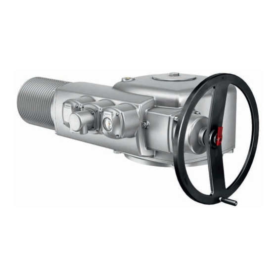
A multi-turn actuator is an actuator which transmits torque to the valve or the valve gearbox for at least one revolution and can be capable of withstanding thrust. AUMA multi-turn actuator Figure 1: Example of AUMA multi-turn actuator SA 25.1 – SA 40.1 and SA 48.1 SA 25.1 – SA 40.1 SA 48.1 Motor Electrical connection, e.g. -
Page 8: Name Plate
Name plate 3 Name plate Figure 2: Arrangement of name plates Actuator name plate Motor name plate Actuator name plate Figure 3: Actuator name plate (example) [12] [13] [10] [11] Name of manufacturer Address of manufacturer Type designation Order number Serial number Speed Torque range in direction CLOSE Torque range in direction OPEN... - Page 9 2024 Year of manufacture = 2024 Data Matrix code When registered as authorised user, you may use our AUMA Assistant App to scan the Data Matrix code and directly access the order-related product documents without having to enter order number or serial number.
-
Page 10: Transport And Storage
Transport and storage 4 Transport and storage 4.1 Transport Actuator For transport to place of installation, use sturdy packaging. Suspended load! DANGER Death or serious injury. à Do NOT stand below suspended load. à Attach ropes or hooks for the purpose of lifting by hoist only to housing and NOT to handwheel. -
Page 11: Storage
SA 48.1 AD... 180-... Refer to motor name plate Indicated weight includes AUMA NORM multi-turn actuator with 3-phase AC motor, electrical connec- tion in standard version, output drive type B1 and handwheel. For other output drive types, consider additional weights. -
Page 12: Assembly
Assembly 5 Assembly 5.1 Mounting position 5.2 Fit handwheel To avoid transport damage, handwheels are supplied separately as appropriate. In this instance, the handwheel must be mounted prior to commissioning. Damage at the change-over mechanism due to incorrect assembly! NOTICE à... -
Page 13: Mount Actuator To Valve
Assembly Figure 10: Secure with retaining ring. 5.3 Mount actuator to valve Corrosion due to damage to paint finish and condensation! NOTICE à Touch up damage to paint finish after work on the device. à After mounting, connect the device immediately to electrical mains to ensure that heater minimises condensation. -
Page 14: Output Drive Type A
Assembly 5.3.2 Output drive type A Figure 11: Design of output drive type A Output mounting flange Stem nut with dog coupling Valve stem Short description Output drive type A consisting of output mounting flange [1] with axial bearing stem nut [2]. The stem nut transmits the torque from the actuator hollow shaft to the valve stem [3]. - Page 15 Assembly 3. Place output drive type A [2] on valve stem and turn until output drive type A [2] is flush on the valve flange [4]. 4. Turn output drive type A [2] until alignment of the fixing holes. 5. Fasten screws [5] between valve and output drive type A [2] without completely tightening them.
- Page 16 5.3.2.2 Finish machining of stem nut for output drive type A This working step is only required if stem nut is supplied unbored or with pilot bore. For exact product version, please refer to the order-related technical data sheet or the AUMA Assistant App.
- Page 17 Assembly Figure 16: Output drive type A [2.1] [2.2] [2.1] [2.1] [2.2] [2.1] Stem nut Axial needle roller bearing [2.1] Axial bearing washer [2.2] Axial needle roller and cage assembly Spigot ring How to proceed 1. Remove spigot ring [3] from output drive. 2.
-
Page 18: Output Drive Types B/C/D/E
Assembly 5.3.3 Output drive types B/C/D/E Figure 17: Example of output drive type B [2*] Multi-turn actuator flange For output drive types B/B1/B2 hollow shaft with keyway [2*] For output drive types B3/B4/E, an out- Gearbox/valve shaft with parallel key put drive sleeve is fitted into the hollow shaft Spigot at valve flanges should be loose fit. -
Page 19: Accessories For Assembly
Assembly 6. Fasten screws [4] crosswise with a torque according to table Tightening torques for screws [} 53]. 5.4 Accessories for assembly 5.4.1 Stem protection tube for rising valve stem Figure 19: Assembly of the stem protection tube [1]* [1]** Protective cap for stem protection tube [1]* Option for size 25.1: Protective cap (fitted) - Page 20 Assembly 4. Check whether protective cap [1] for stem protection tube is available, in perfect condition and tightly placed on or screwed to the tube.
-
Page 21: Electrical Connection
It can also be requested from AUMA when indicating the order number (refer to name plate) or downloaded directly from our Website (http://www.auma.com). Valve damage when connecting to actuator controls! NOTICE à... -
Page 22: Motor Connection
For connecting position transmitters, only use screened cables. 6.2 Motor connection Figure 22: Arrangement of connections at actuator SA 25.1 ‒ SA 40.1 SA 48.1 AUMA plug/socket connector for con- Motor connection for motor connections trol connections and motor connections exceeding 25 A up to 25 A... -
Page 23: Open Motor Connection Compartment
Electrical connection 6.2.1 Open motor connection compartment Figure 23: Open motor connection compartment SA 25.1 – SA 40.1 SA 48.1 Cover Screws O-ring Cable gland Electric shock due to presence of hazardous voltage! DANGER Death or serious injury. à Disconnect device from the mains before opening. Corrosion by ingress of humidity when using unsuitable cable glands/ NOTICE blanking plugs! -
Page 24: Connect Motor Cables
Electrical connection 6.2.2 Connect motor cables Table 7: Terminal cross sections and terminal tightening torques Type Speed Terminal cross sections Tightening torques 4 – 22 0.5 – 16 mm 2.0 Nm SA 25.1 SAR 25.1 32 – 90 2.5 – 35 mm 3.5 Nm 4 – 22 4 –... -
Page 25: Close Motor Connection Compartment
3. Apply a thin film of non-acidic grease (e.g. petroleum jelly) to the O-ring and insert it correctly. 4. Fit cover [1] and fasten screws [2] evenly crosswise. 6.3 S/SH electrical connection (AUMA plug/socket connector) Figure 26: S and SH electrical connection Cover... -
Page 26: Open Terminal Compartment
Control contacts also available as crimp-type connection as an option. S version (standard) with three cable entries. SH version (enlarged) with additional cable entries. For cable connection, remove the AUMA plug/socket connector and the socket carrier from cover. Technical data Table 8: Electrical connection via AUMA plug/socket connector... -
Page 27: Cable Connection
Electrical connection Figure 28: Example: Name plate for enclosure protection IP68 How to proceed 1. Loosen screws [2] and remove cover [1]. 2. Loosen screws [4] and remove socket carrier [5] from cover [1]. 3. Insert cable glands [8] suitable for connecting cables. 4. -
Page 28: Close Terminal Compartment
Electrical connection Figure 29: Protective earth connection Socket carrier Screw Washer Lock washer PE conduction with ring lugs/loops Protective earth connection 8. For shielded cables: Link the cable shield end via the cable gland to the housing (earthing). 6.3.3 Close terminal compartment Figure 30: Close terminal compartment [4] [5] Cover... -
Page 29: Accessories For Electrical Connection (Option)
Electrical connection 6. Fasten cable glands and blanking plugs applying the specified torque to ensure the required enclosure protection. 6.4 Accessories for electrical connection (option) 6.4.1 Parking frame Figure 31: Parking frame, example with S plug/socket connector and cover Application Parking frame for safe storage of a disconnected plug or cover. For protection against touching the bare contacts and against environmental influ- ences. -
Page 30: External Earth Connection
Electrical connection 6.4.3 External earth connection Figure 33: Earth connection for multi-turn actuator SA 25.1 ‒ SA 40.1 SA 48.1 Application External earth connection (U-bracket) for connection to equipotential compensation. Table 10: Terminal cross sections and earth connection tightening torques Conductor type Terminal cross sections Tightening torques Solid wire and stranded... -
Page 31: Operation
Operation 7 Operation 7.1 Manual operation For purposes of setting and commissioning, in case of motor or power failure, the ac- tuator may be operated manually. Manual operation is engaged by an internal change- over mechanism. Manual operation is automatically disengaged when the motor is started again. The handwheel does not rotate during motor operation. -
Page 32: Motor Operation
Operation Figure 35: Release change-over lever 3. Turn handwheel in desired direction. To close the valve, turn handwheel clockwise: ð Drive shaft (valve) turns clockwise in direction CLOSE. Figure 36: Turn handwheel 7.2 Motor operation Damage at valve due to incorrect setting! NOTICE à... -
Page 33: Indications (Option)
Indications (option) 8 Indications (option) 8.1 Mechanical position indication via indicator mark Figure 37: Mechanical position indicator End position OPEN reached End position CLOSED reached Indicator mark at cover Properties • Independent of power supply • Used as running indication: Indicator disc rotates during actuator operation and continuously indicates the valve position (For “clockwise closing”... -
Page 34: Signals (Output Signals)
Signals (output signals) 9 Signals (output signals) 9.1 Feedback signals from actuator The switches can be provided as single switches (1 NC and 1 NO), as tandem switches (2 NC and 2 NO) or as triple switches (3 NC and 3 NO). The precise ver- sion is indicated in the terminal plan or on the order-related technical data sheet. -
Page 35: Commissioning (Basic Settings)
Commissioning (basic settings) 10 Commissioning (basic settings) 10.1 Open switch compartment The switch compartment must be opened to perform the following settings. How to proceed 1. Loosen screws [2] and remove cover [1] from the switch compartment. Figure 38: Open switch compartment Cover Screws Indicator disc... -
Page 36: Set Limit Switching
Commissioning (basic settings) Figure 40: Torque switching heads Torque switching head black in direc- Torque switching head white in direc- tion CLOSE tion OPEN Lock screws Torque dials How to proceed 1. Loosen both lock screws [3] at the indicator disc. 2. -
Page 37: Set End Position Open (White Section)
Commissioning (basic settings) 4. Press down and turn setting spindle [1] with screwdriver in direction of the arrow and observe the pointer [2]: While a ratchet click is felt and heard, the pointer [2] moves 90° every time. 5. As soon as the pointer [2] is 90° from mark [3]: Continue turning slowly. 6. -
Page 38: Check Direction Of Rotation At Hollow Shaft/Stem
Commissioning (basic settings) Figure 42: Direction of rotation (for “clockwise closing” version) 10.4.2 Check direction of rotation at hollow shaft/stem Figure 43: Direction of rotation of the hollow shaft/stem for operation in direction CLOSE (clock- wise closing version) Threaded plug Seal Hollow shaft Protective cap for stem protection tube stem Stem protection tube... -
Page 39: Check Limit Switching
Commissioning (basic settings) 10.4.3 Check limit switching How to proceed 1. Manually operate actuator into both valve end positions. 2. The limit switching is set correctly if: ð WSR/LSC contact trips in end position CLOSED WOEL/LSO contact trips in end position OPEN ð... -
Page 40: Commissioning (Optional Equipment Settings)
Commissioning (optional equipment settings) 11 Commissioning (optional equipment settings) 11.1 Potentiometer The potentiometer is used as travel sensor and records the valve position. Setting elements The potentiometer is housed in the actuator switch compartment. The switch compart- ment must be opened to perform any settings. Refer to Open switch compartment [} 35]. -
Page 41: Set Measuring Range
Commissioning (optional equipment settings) Power supply possible via: AC, AM actuator controls or external power supply Depending on temperature range of the actuator: refer to name plate Setting elements The RWG is housed in the actuator switch compartment. The switch compartment must be opened to perform any settings. -
Page 42: Set Measuring Range
Commissioning (optional equipment settings) Technical data Table 13: EWG 01.1 Data 3-wire and 4-wire systems 2-wire system Output current I 0 – 20 mA, 4 – 20 mA 4 – 20 mA Power supply U 24 V DC (18 – 32 V) 24 V DC (18 –... -
Page 43: Adjust Current Values
Commissioning (optional equipment settings) a) Measuring range 0/4 – 20 mA as well as measuring range 20 – 0/4 mA (inverse operation) can be set. During setting process, the measuring range (normal or inverse operation) is as- signed to the end positions by push button S1/S2 assignment. b) For 2-wire systems, switch off LED end position signalling prior to setting the measuring range. -
Page 44: Switch On/Off Led End Position Signalling
Commissioning (optional equipment settings) If the current value fluctuates (e.g. between 4.0 – 4.2mA), the Switch on/off LED end position signalling [} 44] must be switched off for current adjustment. How to proceed 1. Operate valve in desired end position (OPEN/CLOSED). 2. -
Page 45: Set Running Direction Close (Black Section)
Commissioning (optional equipment settings) 11.4.1 Set running direction CLOSE (black section) How to proceed 1. Move valve in direction CLOSE to desired intermediate position. 2. If you override the tripping point inadvertently: Move valve in opposite direction and approach intermediate position again in direction CLOSE (always approach the intermediate position in the same direction as in later electrical operation). - Page 46 Commissioning (optional equipment settings) Figure 50: Indication OPEN 6. Move valve to end position CLOSED again. 7. Check settings: If the symbol (CLOSED) is no longer in alignment with mark on the cover: 7.1 Repeat setting. 7.2 Check whether the appropriate reduction gearing has been selected, if re- quired.
-
Page 47: Corrective Actions
0/4 – 20 mA at The LED on the EWG either flashes in setting Request AUMA Service. EWG position transmitter cannot be mode a) single flash or b) triple flash: set. -
Page 48: Motor Protection (Thermal Monitoring)
Corrective actions 12.2 Motor protection (thermal monitoring) PTC thermistors or thermoswitches are provided in the motor winding to monitor the motor winding temperature. Motor protection trips as soon as the max. permissible winding temperature has been reached. Possible causes Overload, running time exceeded, max. number of starts exceeded, max. ambient temperature exceeded. -
Page 49: Servicing And Maintenance
We recommend contacting our service for any interventions. à Only perform servicing and maintenance tasks when the device is switched off. Service & Support AUMA offers extensive service such as servicing and maintenance as well as cus- tomer product training. Contact addresses are indicated on our website (www.auma.com). -
Page 50: Maintenance
Servicing and maintenance 13.2 Maintenance Manual operation During maintenance, the mechanical parts of the handwheel activation, in particular motor coupling, must be checked. Replace the parts in case of visible wear. Lubrication • In the factory, the gear housing is filled with grease. •... -
Page 51: Technical Data
The technical data sheet can be downloaded from our website at http:// www.auma.com in both German and English (please state the order number). 14.1 Technical data Multi-turn actuators Features and functions Certificates are attached to the device. - Page 52 IEC 60664-1 Vibration resistance according to 2 g, 10 to 200 Hz (AUMA NORM), 1 g, 10 to 200 Hz (for actuators with AM or AC actuator controls) IEC 60068-2-6 Resistant to vibration during start-up or for failures of the plant. However, a fatigue strength may not be derived from this.
-
Page 53: Tightening Torques For Screws
Technical data Technical data for limit and torque switches U min. 24 V AC/DC U max. 250 V AC/DC I min. 20 mA I max. AC current 5 A at 250 V (resistive load) 3 A at 250 V (inductive load, cos phi = 0.6) I max. -
Page 54: Spare Parts List
Spare parts list 15 Spare parts list 15.1 Multi-turn actuators SA 25.1 – SA 48.1 S / SAR 25.1 – SAR 30.1 S... - Page 55 Please state device type and our order number (see name plate) when ordering spare parts. Only original AUMA spare parts should be used. Failure to use original spare parts voids the warranty and exempts AUMA from any li- ability. Representation of spare parts may slightly vary from actual delivery.
-
Page 56: Index
44 Ambient temperature 8, 52 Inverse operation (0/20 – 4 mA) 43 Applications 4 Approval plate 9 Assembly 12 AUMA Assistant App 9 LED end position signalling 44 Lifetime 52 Limit switches 21 Limit switching 36, 39 Blanking plug 22 Long-term storage 11... - Page 57 Index 40 RWG position transmitter 40 Safety instructions 4 Safety instructions/warnings 4 Safety standards 22 Screw plugs 22 Serial number 8, 9 Service 49 Service conditions 52 Short-circuit protection 21 Size 9 Spare parts list 54 Speed 8 Standards 4 Stem 38 Stem nut...
- Page 60 AUMA Riester GmbH & Co. KG Location Muellheim PO Box 1362 79373 Muellheim, Germany Tel +49 7631 809 - 0 Fax +49 7631 8091250 info@auma.com www.auma.com Y004.798/003/en/1.24 For detailed information on AUMA products, refer to the Internet: www.auma.com...
Need help?
Do you have a question about the NORM SA 25.1 and is the answer not in the manual?
Questions and answers