
Related Manuals for LEMKEN Solitair DT/600


Summary of Contents for LEMKEN Solitair DT/600
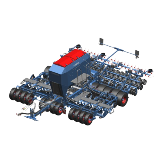
- Page 1 OPERATING INSTRUCTIONS SEEDING COMBINATION SOLITAIR DT Solitair DT/400 Solitair DT/600 en-GB | Item no. 17516084 | BA Rev. 03/2023-05...
- Page 2 Pass these instructions to all users / owners. Original instructions © 2023 | This documentation is copyright protected. The copyright remains with LEMKEN GmbH & Co. KG, Weseler Strasse 5, D-46519 Alpen. The texts, diagrams and drawings must not be duplicated, distributed or disclosed in any other way,...
-
Page 3: Table Of Contents
Table of contents Table of contents About these instructions............................1 1.1 Introduction................................. 1 1.2 Further applicable documents........................3 1.3 Target groups..............................3 1.4 Liability and warranty............................3 1.5 Applied presentations............................. 4 1.5.1 Signal words and hazard statements...................... 4 1.5.2 Symbols and text markings........................5 1.5.3 Direction specifications.......................... - Page 4 Table of contents 3.8.2 Pre-emergence marker..........................35 3.8.3 Distributors..............................36 3.8.4 Trapeze packer roller..........................36 3.8.5 Levelling harrow............................36 3.9 Fertiliser bar............................... 37 3.9.1 Fertiliser coulter............................37 3.10 Operation terminal............................38 Commissioning................................ 39 4.1 Preparing an attachment..........................39 4.1.1 Check machine for completeness......................39 4.1.2 Ensuring suitability of the tractor......................
- Page 5 Table of contents 4.7.3 Setting distribution rate..........................86 4.7.4 Changing parameters of metering units..................... 87 Road travel................................. 88 5.1 Information on road travel........................... 88 5.2 Preparing for road travel..........................88 5.3 Preparing the lighting equipment for road travel................89 Operation................................... 91 6.1 Basic operation..............................
- Page 6 Table of contents 9.1.1 Preparations..............................123 9.1.2 During the maintenance and repair....................124 9.2 Maintenance..............................124 9.2.1 Maintenance schedule..........................124 9.2.2 Tractor connection........................... 126 9.2.3 Trailer................................127 9.2.4 Checking safety devices.......................... 129 9.2.5 Hydraulics..............................130 9.2.6 Electrics................................. 131 9.2.7 Clean compressed air filter........................131 9.2.8 Metering units............................
- Page 7 Table of contents 12.9 Operating materials........................... 156 12.10 Tyres and wheels............................156 12.11 Connecting systems at the machine....................157 12.12 Coulter bar..............................158 12.13 Metering wheel sets..........................158 Index..................................159 Appendix................................. 165 A Type plate variants............................166 B Tightening torques screws .......................... 168 C Calculation of axle load and ballasting for mounted machines.............
- Page 8 Table of contents en-GB | Item no. 17516084 | BA Rev. 03/2023-05...
-
Page 9: About These Instructions
About these instructions About these instructions Introduction These operating instructions are important and belong to the machine's scope of delivery. These operating instructions must be available to the user at the place of use. Always read chapter "Safety" before using the machine for the first time. - Page 10 About these instructions Validity range These operating instructions describe operation of the machine after initial commissioning by the LEMKEN sales partner and handover to the operator. Prior to operation, initial commissioning and instruction in operation, setting/adjustment and maintenance must have been carried out.
-
Page 11: Further Applicable Documents
The documents are regularly updated and brought into line with any changes. The latest versions of the documents can be found in the LEMKEN Online Information System (LEONIS). Users can access LEONIS directly via the QR code or the LEMKEN website. -
Page 12: Applied Presentations
About these instructions Applied presentations 1.5.1 Signal words and hazard statements Warning of personal injury The following signal words and hazard statements are used to label warning signs and to warn of residual risks: Signal word Meaning DANGER Indicates an immediate hazardous situation that may result in serious injury or death. -
Page 13: Symbols And Text Markings
About these instructions 1.5.2 Symbols and text markings Symbol, text Meaning marking In front of and in texts Marking for routine maintenance tasks ● Activities that demand the help of service staff. Listing Position numbers [1], Example: ‘Settings’ Software element Example: [OK] Softkey, key, switch and button [kg]... -
Page 14: Safety
Safety Safety Machine limits Intended use The machine is used for simultaneous seedbed preparation and sowing seeds on agricultural land. In the multi-hopper system version, simultaneous distribution of seeds and fertiliser is possible. It may only be used in accordance with the recognised rules of good agricultural practice. -
Page 15: Requirements Of Operators, Users And Service Personnel
Safety Hazardous area The machine and the area in the immediate vicinity of the machine is deemed a hazardous area. This includes the space over the entire width, length and height of the machine, as well as an additional safety distance of two metres to the machine. -
Page 16: General Safety Information
Safety General safety information Operating instructions The operating instructions are part of the machine. The machine is intended exclusively for use in accordance with these operating instructions. Applications of the machine not described in these oper‐ ating instructions may result in personal injury or death or property damage. - Page 17 Safety Safety equipment Existing and fully functional safety devices protect against death or serious personal injury. Keep the labels legible and renew them, if necessary. ► Replace damaged safety devices. ► Install dismantled safety devices before commissioning. ► Move the safety devices to the protective position. ►...
- Page 18 Safety Hydraulic assembly The hydraulic assembly might be under high pressure. Hydraulic oil leaking under pressure can penetrate through the skin into the body. Injury to body parts, face, eyes and unprotected skin may result. The hydraulic assembly may be hot. The hydraulic oil is harmful to health.
-
Page 19: Safety Information On Hazardous Areas Of The Machine
Safety NO passengers Passengers may fall from the machine and seriously injure themselves. Scattered objects may hit and injure passengers. NEVER allow persons to ride along on the machine. ► Safety information on hazardous areas of the machine Area between the tractor and When standing between the tractor and machine, there is a risk due to machine tractor movements or sudden machine movements. - Page 20 Safety Moving hazardous area The hazardous area of the machine during operation. Moving hazardous area The hazardous area includes the area in driving direction across the entire width of the machine. There must be NO persons in the hazardous area. If there are persons in the hazardous area, may result in death or injury to persons.
- Page 21 Safety Folding range Hazardous areas when folding the implement There should be NO persons present in the folding range. If persons are present in the folding range, it may result in death or serious injury. Lateral sections may, due to their height touch overhead lines during the folding processes and cause flashovers.
- Page 22 Safety Only use designated steps. ► Ensure a three-point contact with steps and handrails: Simultane‐ ► ously two hands and one foot or two feet and one hand on the machine Always keep the steps clean and in proper condition. ►...
-
Page 23: Safety Information On Structural Modifications
Safety Safety information on structural modifications Structural modifications Structural modifications and extensions can impair the functionality and operational safety of the machine. This may result in death or injuries. Auxiliary equipment and spare parts must comply with the manufactur‐ er's requirements. Modifications and conversions may only be carried out with the ►... -
Page 24: Safety Information On Hazardous Substances
Safety Driving behaviour Mounted or trailed machines change the driving characteristics of the tractor. The driving characteristics also depend on the operating status, the filling or loading and on the subsoil. If the driver does not consider changed characteristics, accidents may occur. - Page 25 Safety Dressed seeds In order to protect seeds from fungal infestation, diseases or pests, some seeds are dressed with pesticides. The dressing agent encloses the seed. Due to friction between the seeds, dressing agent particles get into the air and onto machine. If dressing agent gets onto the skin or into the lungs, it may result in injury.
-
Page 26: Design And Description
Design and description Design and description Machine overview INFORMATION The machines can be equipped differently at the factory. – Standard components, special equipment or optional accessories are not marked separately. – Contents in this document may differ from the actual equipment of the machine. - Page 27 Design and description Version 6 m 10 Pre-emergence marker Connecting system: Ä Description see page 27 11 Coulter bar Ä Description see page 34 - Headstock - Ball-shaped coupling (not shown) 12 Levelling and row pre-consolidation: - Drawbar eye (not shown) - Trapeze packer roller Type plate - Tyre packer harrow (not shown)
-
Page 28: Machine Safety
Design and description Machine safety 3.2.1 Position of the label 3.2.2 Meaning of the labels This section explains the information and warning signs that have been affixed to the machine. en-GB | Item no. 17516084 | BA Rev. 03/2023-05... - Page 29 Design and description Reading the operating instructions Incorrect use or operation of the machine can result in death or serious injury. Before commissioning: Read and observe the operating instructions. ► Follow the instructions for action. ► Turn off the engine A tractor with the engine running can cause unintentional movements.
- Page 30 Design and description Hydraulic equipment Green +/- Lifting Heliodor working section, leading tools, coulter bar, fertiliser bar, levelling tine section Swivelling in track markers Folding Orange P Hydraulic motor for fan (supply) White T Hydraulic motor for fan (return line - pressureless) Black +/- Hydraulic depth adjustment of the working sections Violet +/-...
-
Page 31: Safety Devices
Design and description Height adjustment of coulter frame (variant with trapeze packer roller) Height adjustment (mechanical) 1 – smallest coulter frame height 5 – largest coulter frame height Depth adjustment of coulter frame (variant without trapeze packer roller) Depth adjustment (mechanical) 1 –... - Page 32 Design and description Rear lighting equipment Warning board Lateral reflectors LED lighting equipment Reflector (triangle) Reflector (round) (not shown) Warning board Depending on national regulations, a warning board may be required for slow-moving vehicles. 3.2.3.2 Lateral safety guards In transport position, protective gratings offer protection against pro‐ truding outer edges.
- Page 33 Design and description 3.2.3.3 Stabilisation Stand for machines with lower link/ three-point linkage Stand The stand ensures that the dismantled machine is stable. When mounted, the stand is folded up. The wheel chocks are carried on the machine in the area of the lamp holder when the machine is mounted.
- Page 34 Design and description 3.2.3.4 Protection against unauthorised use The protection against unauthorised use ensures that only authorised persons can attach the machine to a tractor. The following versions are available: for cross shafts for ball-shaped couplings for drawbar eyes 3.2.3.5 Safety chain For machines without a braking system, a safety chain may be required, depending on the national regulations.
-
Page 35: Connecting Systems
Design and description Connecting systems The approved options for connecting the machine to the tractor are shown in the technical data. Ä Chapter 12.11 ‘Connecting systems at the machine’ on page 157 The machine may be equipped with the following connecting systems: Headstock The headstock with cross shaft and top link pin has been designed according to standard ISO 730. -
Page 36: Trailer
Design and description Ball-shaped coupling Ball-shaped coupling Trailer The middle part of the tyre packer roller also serves as the trailer for this machine. Ä Tyre packer roller. The machine may additionally be equipped with a Ä Compressed air brake. INFORMATION Observe the technical data of the machine: Ä... -
Page 37: Compressed Air Brake
Design and description 3.4.3 Compressed air brake The compressed air brake has the following brake functions: Service brake Parking brake Rapid emergency brake Overview Compressed air tank Drain valve Manoeuvring valve (double release valve) Park valve (double release valve) Brake force regulator en-GB | Item no. -
Page 38: Heliodor Working Section
Design and description Brake cylinder Piston rod Brake lever Guiding screw retainer Guiding screw Brake linkage Heliodor working section The working section can be equipped with the following tools: Side shield Concave discs Side shields limit soil flow to the working width of the machine Leading tyre packer roller and ensure uniform edge levelling. -
Page 39: Hopper
Design and description Hopper 3.6.1 Hopper systems Seed hopper (suction system) Tank Tarpaulin cover Working light Metering unit Fan with air filter Hopper light Level sensors (not shown) en-GB | Item no. 17516084 | BA Rev. 03/2023-05... -
Page 40: Electronic Level Indicator
Design and description Multi-hopper system (pressure tank system) Seed hopper The multi-hopper system offers enhanced deposition procedures. The Separation plate user can distribute two different seeds, seed mixtures or seeds and Closing slide fertiliser at the same time. Chamber A Hopper equipment: Chamber B Two-part hopper... -
Page 41: Pushbutton For Remaining Quantity Discharge
Design and description 3.6.3 Pushbutton for remaining quantity discharge 1 T he user can use the pushbutton to start and stop the remaining quantity discharge. 3.6.4 Fan with air filter Seeds are conveyed to the seeding coulters by an airflow from the fan. The filter protects the system against dust accumulation. -
Page 42: Filling Screw
Design and description Filling screw Funnel The filling screw is used to fill the hopper with seeds or fertiliser. Coulter bar The coulter bar can be equipped with various tools. Pre-emergence markers Distributors Trapeze packer rollers Double disc coulters Pressure rollers Levelling harrow en-GB | Item no. -
Page 43: Seeding Coulter
Design and description 3.8.1 Seeding coulter Pressure roller Self-adjusting scraper of the double disc coulter Double disc coulter Scraper of the pressure roller Double disc coulters with pressure rollers are used to sow seeds in the soil. Versions: Scraper for double disc coulters Solid plastic scraper Plastic scraper with carbide plates around the edge Scraper for pressure rollers... -
Page 44: Distributors
Design and description Application of the short equipment: Machine without levelling harrow 3.8.3 Distributors The distribution is conveyed to the seeding coulter via separate distrib‐ Distributors utors 3.8.4 Trapeze packer roller Trapeze packer roller The trapeze packer roller provides additional row-dependent recon‐ solidation of the soil and precise depth control of the seeding coulters. -
Page 45: Fertiliser Bar
Design and description Fertiliser bar In the fertiliser version, the machine is equipped with a fertiliser bar and a distributor. Fertiliser coulters are used to distribute fertiliser in the soil. Fertiliser bar Distributors Fertiliser coulter 3.9.1 Fertiliser coulter Outlet Scraper Double disc coulter Double disc coulters are used to distribute fertiliser in the soil. -
Page 46: Operation Terminal
Design and description 3.10 Operation terminal LEMKEN machines with electronic control are operated via an opera‐ tion terminal in the tractor. INFORMATION Some machine functions cannot be operated via the operation terminal. These functions are operated for example via the control centre on the machine. -
Page 47: Commissioning
Scope of delivery and equipment of the machine may vary depending on the configuration of the purchase order. 1. Make certain that all LEMKEN original parts are present according to the purchase order. 2. Make certain that all parts are undamaged and correctly mounted (see corresponding mounting instructions if applicable). - Page 48 Commissioning Machine with headstock Checklist Tractor power Ä Performance data, page 153 The tractor power must be within the permitted power range. The tractor power must be sufficient for the consumers of the connected machine, e.g., hydraulic connections. Three-point linkages Ä...
-
Page 49: Dewintering The Machine
Commissioning WARNING Risk of accident due to the machine tipping over If the tractor’s lifting rods are not set rigidly and the slots are not locked, the machine may tip over at the borders. – Set the lifting rods rigidly. –... -
Page 50: Preparing Braking System
Commissioning 4.1.4 Preparing braking system INFORMATION Observe the technical data of the machine: Ä Chapter 12 ‘Technical data’ on page 152 4.1.4.1 Preparing brake cylinder of compressed air brake DANGER Risk of accident due to deactivated brake cylinders For unloading and manoeuvring without a compressed air supply, the brake cylinders and thus the entire com‐... -
Page 51: Attaching The Machine
Commissioning 5. Insert the guiding screw into the retainer at the brake cylinder. 6. Secure the guiding screw with a peg and nut. Brake cylinder Attaching the machine Piston rod Brake lever Preparing the tractor and machine Guiding screw retainer 1. -
Page 52: Single-Point Connection
Commissioning 7. Lift the lower link slightly. 8. Release the top link pin at the pivot bearing Top link pin 9. Select attachment position for the top link Pivot bearing 10. Adjust the length of the top link parallel to the lower links ATTENTION: Damage to the pivot bearing due to incorrect top link length 11. - Page 53 Commissioning Checking height of the traction device The height of the traction device of the machine must match the height of the ball-shaped coupling of the tractor. Precondition: √ The machine is aligned parallel to the subsoil. 1. Check whether the heights of the traction device of the machine and the ball-shaped coupling of the tractor match.
- Page 54 Commissioning 5. Insert the pin through the tractor drawbar and the drawbar 6. Secure the pin Ä ‘Connect lines and hoses’ on page 47 INFORMATION: Ensure that the hydraulic connections and hydraulic plugs are clean. 8. Use the crank to raise the stand of the machine up to the stop. ð...
-
Page 55: Line And Hoses
Commissioning 10. Use the crank to raise the support of the machine up to the stop. ð Machine is attached to the tractor. 4.2.3 Line and hoses Connect lines and hoses 1. Secure the tractor against rolling away. WARNING: When standing between the tractor and machine, there is a risk of the tractor rolling away or of sudden machine movements. - Page 56 Commissioning The user must attach the safety chain in such a way that: when the machine is detached from the tractor, the machine cannot hit the ground. the steering angle of the machine is not restricted. the safety chain does not sag more than necessary. when the machine is lifted, correct functioning of the machine is not restricted.
-
Page 57: Filling The Hopper
Commissioning 5. Press the pin inwards. 6. Push the locking device towards the hook 7. Check the attachment of the safety chain 8. Check the locking device of the hook Filling the hopper Locking device Hook 4.3.1 Manually filling the hopper Chain Preconditions: √... -
Page 58: Filling The Hopper Using The Filling Screw
Commissioning 3. Enter the platform via the step. 4. Open the cover or the roller tarpaulin cover. ATTENTION: The filling screen at the edge of the hopper is NOT intended for larger loads. – Do NOT step on the filling screens. –... - Page 59 Commissioning √ Suitable metering wheel sets have been mounted. √ Levers are in position 1 to 3. 1. Follow the seed producer's instructions for handling seeds. If necessary, use protective gear. CAUTION: Dust from spreading material can result in damage to health.
- Page 60 Commissioning 3. To fold out the guide arm of the filling screw, push the lever of the valve combination to the left. Valve combination lever 1 ð The guide arm of the filling screw folds out. Filling screw 4. Shortly before reaching the end position: Guide arm Swing out the holder manually.
- Page 61 Commissioning 6. Manually fold the filling screw on the guide arm from transport position to filling position. Filling screw 7. Make sure the link of the filling screw is located in one of the three Guide arm detent positions of the guide arm . 8.
- Page 62 Commissioning 10. To activate the hydraulics of the filling screw, push the lever of the valve combination to the left. Valve combination lever 2 11. To start the filling screw, change the 3/2 directional control valve . 3/2 directional control valve 12.
- Page 63 Commissioning 13. After the filling procedure, stop the filling screw using the 3/2 directional control valve . 14. With a double hopper Swing the filling screw. Fill the second half of the hopper. 3/2 directional control valve 15. To deactivate the hydraulics of the filling screw, push the lever of the valve combination to the right.
- Page 64 Commissioning Folding in the filling screw Preconditions: √ The filling procedure has been completed. √ The remaining quantity of the filling material has been removed from the filling screw. √ Tractor-machine combination is secured against rolling away. 1. To be able to close the cover : Swing out the filling screw to the side.
- Page 65 Commissioning 5. To fold in the guide arm of the filling screw, push the lever of the valve combination to the right. 6. Fold up the guide arm slightly. Valve combination lever 1 7. Allow the pipe clamp of the holder to engage in the bushing of the guide arm .
-
Page 66: Preparing The Machine For Use
Commissioning 9. To change the hydraulics from filling screw to fan, actuate the lever on the 3/2 directional control valve . 3/2 directional control valve Preparing the machine for use 4.4.1 Preparations 1. Park the machine. 2. Secure the machine to prevent it from rolling away. 3. -
Page 67: Adjusting Working Section
Commissioning Rolling circumference of tyres [2575 mm – 2825 mm] Adjustment Actual axle load [kg] From 1 (locked) 2 (locked) 3 (locked) 4500 5600 5601 7500 7501 9000 9001 11000 4.4.3 Adjusting working section Infinitely variable hydraulic working Remotely controllable, infinitely variable hydraulic adjustment depth adjustment Max. - Page 68 Commissioning To adapt the side shields to the desired working width: 1. Undo the screws 2. Move the side shield onto the carrier. 3. Tighten the screws. Ä Appendix B ‘Tightening torques screws ’ on page 168 ATTENTION: Avoid damage to the platform or side shield. –...
-
Page 69: Adjusting The Fan Speed
Commissioning 4.4.4 Adjusting the fan speed During attachment, the user adjusts the fan to the desired speed. The fan speed is displayed on the operation terminal. INFORMATION Observe the operating instructions for the control. If the fan speed fluctuates during sowing and this causes the overpres‐ sure to fall, the user must readjust the fan speed. - Page 70 Commissioning INFORMATION Speeds, which are too high or too low, may negatively affect the longitudinal distribution and cross distribution. If speeds are too low, distributors and feed lines may become blocked. When the operating temperature of the hydraulic oil has been reached: –...
- Page 71 Commissioning Adjustment with volumetric flow con‐ trol and flow control valve Precondition: √ The additional tractor control unit for the fan drive has volumetric flow control. √ A flow control valve is mounted on the machine. 1. At the machine: Open the flow control valve fully.
- Page 72 Commissioning 5. If fluctuations continue to occur at the fan: Open the flow control valve fully. Increase the fan speed on the additional tractor control unit by 1000 rpm. Use the flow control valve to reduce the speed to the desired speed.
-
Page 73: Adjusting Air Duct
Commissioning 4.4.5 Adjusting air duct Air distributor With a multi-hopper system, the user adjusts the air duct for the distri‐ Detent lever bution at the air distributor . With the air duct, the user defines the 90:10 ratio desired ratio of the contents of chamber B to chamber A. 50:50 ratio 30:70 ratio INFORMATION... -
Page 74: Setting Level Indicator
Commissioning 4.4.6 Setting level indicator To monitor the level of the hopper, the sensor can be placed at three height positions The user can reposition the sensor when changing the spreading mate‐ rial. 1. Remove the sensor. Undo the union nut at the holder Pull the sensor out of the holder. - Page 75 Commissioning Moving the pre-emergence marker on the carrier 1. Undo the U-bolts on the carrier of the pre-emergence marker. 2. Move the pre-emergence marker on the carrier to the desired track gauge. 3. Tighten the U-bolts on the carrier in a criss-cross manner. Carrier U-bolt Adjusting the concave disc on the disc...
-
Page 76: Adjusting Bottom Gates
Commissioning 4.4.8 Adjusting bottom gates Handle To ensure gentle distribution, adjustable bottom gates are arranged Detent position under the metering wheel sets. The handle can be used to switch Bottom gate the bottom gates in increments into three detent positions Before filling the hopper: ►... - Page 77 Commissioning 4.4.9.1 Loosening tracks with cutting discs The wheelmark eradicator disc is mounted on the holder with U- bolts and a clamping plate Adjusting lateral position 1. Undo the nuts of the U-bolts 2. Slide the wheelmark eradicator disc into the corresponding position on the holder.
-
Page 78: Adjusting The Track Markers
Commissioning Adjusting the working depth of the wheelmark eradicators The adjustable spring tines of the concave discs in the tractor Spring tines track can be attached in three different positions: Concave disc Basic position The concave discs in the tractor track work at exactly the same depth as the remaining concave discs. -
Page 79: Changing The Setup State
Commissioning Precondition: √ The control is switched off. 1. Undo the screw 2. Position the track marker on the stop arm. 3. Tighten the screw. Ä Appendix B ‘Tightening torques screws ’ on page 168 4. Undo the screws 5. Rotate the track marker to the desired pitch angle. The pitch angle can be read on the scale Track marker 6. - Page 80 Commissioning Removing metering wheel set Precondition: √ The hopper has been emptied. √ When the hopper is full, the plug is inserted into the housing against the closing slide. Housing 1. To release it from the detent position, pull the handle of the Bottom gate lever Handle...
- Page 81 Commissioning Aligning metering wheel set 1. Place the new metering wheel set onto the metering shaft 2. Turn the metering wheel until all the springs of the metering wheel are in alignment. 3. Slide the metering wheel set further onto the metering shaft. While doing so, insert the springs of the metering wheels into the groove of the housing...
-
Page 82: Adapting The Tramline Mechanism
Commissioning 2. Close the bottom gate with the lever 3. Remove the closing slide. 4. Insert the plug 5. Store the removed metering wheel set in a dust and water-proof box. Bottom gate lever 4.5.2 Adapting the tramline mechanism Plug Adjusting the tramline width Adapt the tramline width to the track width of the cultivating machine: 1. -
Page 83: Preparing Control For Use
Commissioning Changing the distributor cartridge 1. Undo the star grips . Fold down the star grip to the side. 2. Remove the cover Star grip 3. Remove the nuts Cover 4. Remove the existing distributor cartridge 5. Mount the new distributor cartridge. Pay attention to the marking of the hoses for tramlines. -
Page 84: Performing Calibration Test
Commissioning Performing calibration test 4.7.1 Calibration process Background In order to determine the rate of seeds or fertiliser for the distribution, the user must carry out a calibration test. In the calibration test, the distribution is simulated for a defined period of time. - Page 85 Commissioning Preparing the machine 1. Park the tractor-machine combination and secure it against rolling away. 2. Switch off the fan. 3. Lift the machine via the additional tractor control unit. 4. Determine the tare weight of the calibration tray Set the scales to zero. Weigh the empty calibration tray.
- Page 86 Commissioning 9. To switch on the agitator shafts: Remove the linch pins and the switching rings. Install the switching rings with the springs in the grooves of the gear wheels. Install the linch pin in the switching ring and hole of the agitator shaft.
- Page 87 Commissioning 2. With one multi-hopper system: Use the buttons to set the hopper and deposition: – Seeds – Fertiliser – Nothing Call up calibration test: – Button : Calibration test for hopper B – Button : Calibration test for hopper A ð...
- Page 88 Commissioning 4. Continue process. ð The page with the recommended factory setting for the pre‐ viously set parameters opens. The factory settings depend on the selected spreading material. Number of metering wheels of a metering wheel set Detent position of the bottom gate on the machine Agitator shaft status For some spreading materials, the agitator shaft must be turned off.
- Page 89 Commissioning 3. In the control: Start the filling process of the metering units. ð At the machine: Turn the metering wheel sets. ð In the control: The page with the following text opens. 1. Wait until all metering units have been filled. 2.
- Page 90 2. Place the calibration tray under the metering units with the bottom facing upwards. 3. Attach the calibration tray to the magnet. 4. When the LEMKEN scales were used: Remove the LEMKEN scales and put them back in the case. Terminate calibration test 1.
- Page 91 Commissioning 2. Continue process. ð The page opens. 3. In case of doubt or for checking purposes, repeat the calibration test via the button . Perform the calibration test again from Ä Procedure step 1 on page 79. 4. Terminate the calibration test via the button . ð...
-
Page 92: Setting Spreading Material Parameters
Commissioning 4.7.2 Setting spreading material parameters In the setting parameters: 1. Select the spreading material in the field Alternatively: Ä Setting up own spreading material Select. 2. Enter the specific weight of the seeds or fertiliser via the button ð The settings open. 3. - Page 93 Commissioning Setting up own spreading material The user can freely assign the memory locations 1...3 for their own spreading material. 1. Select a free memory location. ð The settings open. 2. Call up further setting options via the button ð The settings open. 3.
-
Page 94: Setting Distribution Rate
Commissioning 4.7.3 Setting distribution rate In the setting parameters: ► Enter the distribution rate in the field [kg/ha]. If the unit of measurement is not available: 1. Call up the converter for the distribution rate. ð The converter opens. 2. Enter parameters. Enter grains per m Enter thousand grain weight [g]. -
Page 95: Changing Parameters Of Metering Units
Commissioning 4.7.4 Changing parameters of metering units The page with the parameters of the metering units opens after the spreading material setting. The factory settings for the metering units show the preset parameters for the set spreading material. INFORMATION Seedtables Information on the following parameters is stored in the seedtables: –... -
Page 96: Road Travel
Road travel Road travel Information on road travel INFORMATION Laws on driving on public roads differ in many countries. Pay particular attention to local laws and regulations regarding the ► following points: Driving on public highways Maximum permissible transport height Maximum permissible transport width Maximum permissible transport weight Lighting equipment... -
Page 97: Preparing The Lighting Equipment For Road Travel
Road travel Checklist Hydraulic locking of the lateral sections If the machine is foldable, the machine must be folded in and in transport position secured. The lateral sections DO NOT fold out automatically and WITHOUT user intervention. The machine remains permanently in the transport position. Stands The stands are folded in. - Page 98 Road travel Checking electric lines and proper functioning 1. Connect the connector of the lighting equipment to the socket on the tractor. 2. Test the electric line between the tractor and the machine. 3. Test the lighting equipment. Testing the lighting equipment 1.
-
Page 99: Operation
Operation Operation Basic operation 6.1.1 Mounting the safety guard Before driving on public roads, cover machine parts with a safety guard: Wheelmark eradicator discs and track levelling plates 1. Attach the protective grating to the holder provided using a pin. 2. - Page 100 Operation Preconditions: Machine mounted properly NO overhead lines in the folding range NO persons in the folding range Sufficient free space for folding the track markers Sufficient free space for the lift height Tractor has stopped. Fan is switched off. Safety guards have been dismantled.
- Page 101 Operation Folding machine in Prior to one-sided folding in √ The machine has been folded out Close the shut-off valve on the basic frame , on the right next to ► the platform grate . ð The hydraulics for folding the left side is locked. Shut-off valve Basic frame Folding the machine in...
-
Page 102: Operate The Compressed Air Brake
Operation Prepare the machine. Check it for safety. Ä Chapter 5 ‘Road travel’ on page 88 Folding machine out Prior to one-sided folding out √ Machine has been folded in on one side Open the shut-off valve on the basic frame , on the right next to ►... - Page 103 Operation Couple and uncouple the brake hoses Couple the brake hoses 1. Couple the yellow brake coupling (compressed air control line) to the tractor. 2. Couple the red brake coupling (compressed air supply line) to the tractor. YELLOW Uncouple the brake hoses 1.
- Page 104 Operation Operate the parking brake The parking brake is used by the user to secure the machine against rolling away. Releasing the parking brake 1. Push in the red button of the park valve . 2. Check adjustment of the brake force regulator. If necessary, adjust the setting to the axle load of the machine.
-
Page 105: Operate The Stand
Operation 6.1.4 Operate the stand 6.1.4.1 Stand of three-point connection Folding out stand Precondition: √ The machine has been secured against rolling away. 1. Lift the machine approx. 1...5 cm. 2. Remove the pin 3. Swivel down the stand 4. Secure the stand with the pin in the hole 5. - Page 106 Operation 6.1.4.2 Stand of single-point connection Lowering stand with the crank Precondition: √ The machine has been secured against rolling away. 1. Remove the pin 2. Lower the stand with the crank With drawbar eyes, lower to the subsoil to relieve the double lashing tractor drawbar on the tractor.
-
Page 107: Securing And Unlocking Track Markers
Operation 6.1.5 Securing and unlocking track markers The track markers must be folded in and secured prior to transport. Holder After transport, the track markers must be unlocked for working in the Parking position field. Spring pin Unlocking track markers 1. -
Page 108: Adjusting The Machine
Operation Folding in pre-emergence marker For the transport position, the pre-emergence marker must be folded 1. Remove the pin and the linch pin. 2. Swivel in the arm 3. Secure the position of the arm with the bolt and linch pin. Folding out pre-emergence marker For the operating position, the pre-emergence marker must be folded out. -
Page 109: Adjusting The Working Depth Of The Working Section
Operation Precondition: √ Machine is standing on flat and level subsoil. 1. With three-point connection, the machine is aligned by adjusting the height of the tractor's lower links. 2. With single-point connection, the machine is aligned by adjusting the height of the coupling device. 3. -
Page 110: Adjusting The Working Depth Of The Front Tyre Packer Roller
Operation Lift limitation with HydroClips CAUTION Risk of crushing The HydroClips are under spring tension during installa‐ tion. If the HydroClips snap back uncontrollably, there is a risk of injury to hands and fingers. – Install the HydroClips in a controlled manner using both hands. - Page 111 Operation The machine is standing on a flat and level surface. 1. Lift the tyre packer rollers via the hydraulic rams until the pins are relieved. Front tyre packer roller 2. If necessary, remove the pin from the parking position ð...
-
Page 112: Adjusting Seed Deposition Depth
Operation Pressure-controlled working depth INFORMATION The height of all elements of the front tyre packer roller must be adjusted to the lowest lug position Precondition: √ The machine is standing on a flat and level surface. 1. Check that all the elements of the front tyre packer roller are adjusted to the lowest lug position 2. -
Page 113: Adjusting Fertiliser Deposition Depth
Operation 6.2.5 Adjusting fertiliser deposition depth Lift limitation with Hydro-Clips The deposition depth is adjusted via Hydro-Clips. The deposition depth depends on the intended use, see the data sheet for the fertiliser. Adjustment recommendation: 5 cm deeper than the seed deposi‐ tion CAUTION Risk of crushing... -
Page 114: Adjusting The Coulter Pressure
Operation 6.2.6 Adjusting the coulter pressure 6.2.6.1 OptiDisc M double disc coulters The coulter pressure can be adjusted mechanically at the double disc Compression spring Adjusting lever coulter via tow bars with a compression spring The tensioning force of the compression spring can be gradually increased or reduced via the adjusting lever A special wrench (wrench size 24 mm) is required for the adjustment. - Page 115 Operation Reducing the coulter pressure To reduce the coulter pressure, relieve the compression spring: 1. Place the wrench on the adjusting lever. 2. To relieve the folding clamp: Slightly turn the wrench anti-clockwise. 3. Open the folding clamp. 4. Turn the wrench clockwise. 5.
-
Page 116: Adjusting Coulter Pressure Of Fertiliser Coulter
Operation 6.2.7 Adjusting coulter pressure of fertiliser coulter To maintain the deposition depth of the fertiliser, pressure is exerted Spring on each individual fertiliser coulter by means of a spring . The pres‐ sure is set depending on the soil properties and operating conditions. If excess load is exerted on a share, e.g. -
Page 117: Adjusting The Working Depth Of The Tyre Packer Harrow
Operation 6.2.8 Adjusting the working depth of the tyre packer harrow To adjust the depth of the tyre packer harrows segment by segment: 1. Remove the linch pin 2. Use the hexagon nut to rotate the adjusting tube of the tyre packer harrow ð... - Page 118 Operation Positioning the machine 1. Position the tractor-machine combination. 2. Fold out machine. 3. Switch on the fan. 4. If required: Activate the track markers. 5. Lower the working tools. Sowing 1. Drive the tractor at the permitted driving speed over the cultivated area.
- Page 119 Operation Monitoring sowing 1. Use the control to monitor the distribution rate for sowing. If neces‐ sary, adapt the distribution rate. Softkey Adaptation Increase rate. Reduce rate. Reset rate to target rate. 2. Monitor fan speed. When the fan speed drops: Increase the fan speed.
- Page 120 Operation 5. Observe the position of the machine on the ground. Operating track markers The respective mode of the track markers is preselected in the control of the machine. The folding function of the track markers is carried out via the additional tractor control unit. Short-term manual mode In order to fold the track marker manually during distribution in excep‐...
- Page 121 Operation Semi-automatic mode To select the side on which the track marker will fold out the next time it is lowered: Press the respective track marker button briefly. ► ð The letter is displayed in blue. ð The selected track marker is folded next. ð...
-
Page 122: Interrupting Work
Operation 6.3.2 Interrupting work If one of the following cases occurs: Machine is not responding as it normally does. Machine is blocked. A component of the machine has come loose. 1. Stop the tractor-machine combination. 2. Switch off everything. 3. Check the machine. 4. -
Page 123: Cleaning And Care
Cleaning and care Cleaning and care Cleaning the machine Cleaning intervals Recommendation: After every use When there is a seed change After the season CAUTION Dressed seeds Dust from untreated or dressed seeds can result in damage to health. – When cleaning: Wear protective clothing. -
Page 124: Emptying The Hopper
Cleaning and care Emptying the hopper The user can empty the hoppers as follows, depending on the remaining quantity: Larger remaining quantities: Ä Emptying single tank via outlet Smaller quantities: Ä Chapter 7.2.3 ‘Remaining quantity discharge via metering units’ on page 117 7.2.1 Emptying single tank via outlet Larger remaining quantities in the hopper can be emptied via the... -
Page 125: Emptying Double Hopper Via Camlock Outlet
Cleaning and care 7.2.2 Emptying double hopper via camlock outlet Emptying Larger remaining quantities in the double hopper can be emptied via the camlock outlets 1. Place a collector under the respective camlock outlet . (Not included in the scope of delivery) Camlock outlet 2. - Page 126 Cleaning and care 4. Position the calibration tray under the metering units Calibration tray 5. Open the metering flaps with the lever Metering units Discharging metering units INFORMATION The remaining quantity discharge menu can be called up via the control of the operation terminal, the calibration terminal and the APP.
- Page 127 Cleaning and care 1. Call up the menu for discharging remaining quantities in the set‐ tings. ð With a multi-hopper system: The settings open. Select remaining quantity discharge for hopper B or A. Settings | Remaining quantity discharge ð The page with the following text opens. - After activating remaining quantity discharge, perform a new calibration test.
- Page 128 Cleaning and care 3. Continue process. ð At the machine: The metering wheel sets are turning. ð The page with the following text opens. Remaining quantity discharge is running. - If required: Stop the process via the softkey or button. The discharge time has been preset to 999 seconds.
- Page 129 Cleaning and care After discharge 1. At the machine: Close the metering flaps with the lever ð The remaining quantity discharge via the metering units has been completed. 2. Discharge the calibration tray. 3. Place the calibration tray under the metering units with the bottom facing upwards.
-
Page 130: Detaching Machine
Detaching machine Detaching machine Preparing detaching 1. Move the machine to a parking place with a level surface with sufficient bearing capacity. WARNING: A folded in machine may overturn after being parked on UNSUITABLE subsoil. 2. Lower the stands. Ä See page 97 3. -
Page 131: Maintenance And Repair Work
Maintenance and repair work Maintenance and repair work Maintaining the machine properly Personnel Certain activities, e.g. working on hydraulic hoses, should only be car‐ ried out by service personnel. These tasks are: Highlighted with the symbol Marked in the SERVICE PERSONNEL column in the maintenance schedule 9.1.1 Preparations... -
Page 132: During The Maintenance And Repair
Maintenance and repair work 9.1.2 During the maintenance and repair To prevent accidents or injuries: Wear protective equipment. ► Use auxiliary equipment, e.g.: ► Suitable tools Climbing aids Supporting elements For dismantling and mounting heavy components: ► Use hoisting gear. Check nuts and screw heads etc. - Page 133 Maintenance and repair work Chap. Task to execute 9.2.3.2 Maintaining braking system ● ● 9.2.3.2 Check the compressed air couplings ● ● 9.2.4 Checking the lighting equipment ● 9.2.4 Check marking ● 9.2.4 Checking safety sticker ● 9.2.5 Checking hydraulic hoses ●...
-
Page 134: Tractor Connection
Maintenance and repair work 9.2.2 Tractor connection Checking the top link pin 1. Visual inspection of the top link pin for: Damage Wear 2. Replace damaged or worn top link pins. Checking the cross shaft Personnel: Service personnel 1. Visual inspection by the user Wear Damage Peculiarities when driving... -
Page 135: Trailer
Maintenance and repair work 9.2.3 Trailer 9.2.3.1 Tyres and wheels Check tyres Visual inspection ► Damage Wear Replace damaged tyres immediately. Checking air pressure WARNING Risk of accident due to incorrect air pressure Excessive air pressure in the tyres may cause them to burst. -
Page 136: Check The Compressed Air Couplings
Maintenance and repair work Check the compressed air couplings Visual inspection by the user ► Wear Damage Leak tightness Immediately replace damaged, worn or leaky compressed air couplings. 9.2.3.3 Checking tyre packer roller components Checking scrapers 1. Check the distance between the scrapers and the tyre packer rollers. -
Page 137: Checking Safety Devices
Maintenance and repair work Re-adjusting rubber bars 1. Undo the nut and washer . 2. Undo the clamping plate . 3. Re-adjust worn bars. 4. Mount the nut and washer, see Ä Tightening torques screws , page 168. Replacing rubber bars 1. -
Page 138: Hydraulics
Maintenance and repair work 9.2.5 Hydraulics Checking hydraulic hoses 1. Check hydraulic hoses for damage and leakages. ð Replace damaged or defective hydraulic hoses immedi‐ ately. 2. Check date of manufacture of the hydraulic hoses. ð Have hydraulic hoses replaced at the latest after 6 years. Replacing hydraulic hoses Personnel: Service personnel... -
Page 139: Electrics
Maintenance and repair work 9.2.6 Electrics Checking connector plugs and cables Perform visual inspection of the connector plugs and cables. ► Watch for bent or broken contact pins in the plugs. Watch for exposed places in cables. ð Repair damaged connector plugs or cables immediately or have them replaced. - Page 140 Maintenance and repair work Cleaning the filter of the yellow com‐ pressed air coupling 1. Place a collector under the yellow compressed air coupling . Yellow compressed air coupling Allen key 2. Dismantle the compressed air coupling: Screw-in plug Press down the screw-in plug using an Allen key and turn 90° anticlockwise.
- Page 141 Maintenance and repair work 5. Insert the screw-in plug, spring, filter screen and washer into the housing of the coupling head. 6. Mount the compressed air coupling: Press down the screw-in plug using an Allen key and turn 90° clockwise. ð...
- Page 142 Maintenance and repair work 2. Undo the screw . 3. Undo the screw . Screw ð The pretensioned spring presses the components and apart Screw with spring after loosening the screws. Plate 4. Dismantle the components of the filter screen: Cover Spring Loosen both screws in the plate .
- Page 143 Maintenance and repair work 7. Insert the spring and the filter screen into the housing of the coupling head. Spring 8. Mount the plate using the screws . Filter screen The spring presses the plate upwards. Screws 9. Mount the components: Cover 3 Cover Plate...
-
Page 144: Metering Units
Maintenance and repair work After cleaning 1. Couple the compressed air coupling to the tractor in the following order: 1. Yellow 2. Red 2. Start the tractor engine. ð When the tractor engine is running, the braking system is automatically refilled with compressed air. 3. - Page 145 Maintenance and repair work 3. Position the calibration tray under the metering units Calibration tray 4. To open the bottom gates: Metering units Pull the handle of the lever a little forwards. Move the lever clockwise. 5. Clean the metering units with compressed air. Bottom gate lever Handle en-GB | Item no.
-
Page 146: Cleaning Air Filter
Maintenance and repair work After cleaning 1. Close the bottom gate with the lever 2. Remove and empty the calibration tray. 3. Attach the calibration tray in the holder. Bottom gate lever 4. Remove the closing slide. 5. Insert the plug. 9.2.9 Cleaning air filter The fan is equipped with an air filter. -
Page 147: Checking Viewing Hose At Fan
Maintenance and repair work Checking air filter externally 1. Check the protective grating for dirt. 2. Remove coarse dirt from the protective grating Checking proper functioning of air filter 1. Open three clamps 2. Remove the cover Clamps 3. Visual inspection: Cover Check whether the rotary disc can be turned. -
Page 148: Maintaining Seeding Coulters
Maintenance and repair work Precondition: Viewing hose √ The fan is switched off. √ The tractor is switched off. √ The tractor-machine combination has been secured against rolling away. 1. If fitted: Remove filter. 2. If fitted: Remove hood. 3. Check viewing hose 4. -
Page 149: Check And Adjust The Scrapers Of The Pressure Rollers
Maintenance and repair work Replacing scrapers 1. Remove worn scraper from the holder using a screwdriver or pliers. 2. Fit a new scraper on the holder. INFORMATION Reuse scrapers worn on one side by means of reverse installation. 9.2.11.2 Check and adjust the scrapers of the pressure rollers Check scraper 1. -
Page 150: Maintaining Fertiliser Coulters
Maintenance and repair work 9.2.12 Maintaining fertiliser coulters Checking scrapers 1. Check scrapers for wear. 2. Replace worn scrapers. Replacing scrapers Replace scraper when worn: 1. Remove the scraper from the holder using a screwdriver or pliers. 2. Install a new scraper in the holder. Scraper 9.2.13 Checking the pressure of the transport system... -
Page 151: Checking The Distributor
Maintenance and repair work 9.2.14 Checking the distributor Distributor with distributor cartridges Dust collects under the distributor cartridges. The exhaust air hoses convey a large part of the dust from the distributor towards the ground. 1. Unscrew the cover of the distributor. 2. -
Page 152: Lubricating
Maintenance and repair work Lubricating 9.3.1 Lubrication schedule INFORMATION The lubrication points are colour coded on the machine. Chap. Task to execute 9.3.2 Lubricate pivot bearing ● ● 9.3.2 Lubricate the drawbar eye ● ● 9.3.2 Lubricating ball-shaped coupling ● ●... -
Page 153: Lubricating Components Via Grease Nipples
Maintenance and repair work 9.3.2 Lubricating components via grease nipples Lubricate pivot bearing Lubricate 1 lubricating point. ► Lubricate the drawbar eye ► Lubricate 1 lubricating point at the drawbar eye Lubricating point Lubricating ball-shaped coupling Lubricate 1 lubricating point. ►... -
Page 154: Lubricating Hydraulic Rams
Maintenance and repair work Lubricating hydraulic rams Lubricate 2 lubricating points at each hydraulic ram . ► Lubricating brake shaft ► Lubricate all lubricating points of the brake shaft. Grease nipple Lubricating wheel bearings Lubricate the lubricating point on the wheel bearings . ►... -
Page 155: Lubricating Folding Joints
Maintenance and repair work Lubricating folding joints ► Lubricate the lubricating points on the folding joints. Lubricating point Lubricating track markers 1. Lubricate the lubricating points on the joints. Grease nipple 2. Lubricate the lubricating point on the track marker disc. Grease nipple en-GB | Item no. -
Page 156: Grease Components
Maintenance and repair work 9.3.3 Grease components Grease top link pin Dismantle, grease and reassemble the top link pin. ► Grease pin Dismantle pin, grease and reassemble. ► Grease piston rods Grease piston rods with an acid-free grease. ► Grease surfaces Grease uncoated surfaces that can rust. -
Page 157: 10 Troubleshooting And Error Correction
Troubleshooting and error correction 10 Troubleshooting and error correction 10.1 Finding and eliminating errors correctly INFORMATION Necessary deviations from this procedure are described in the respective chapters on troubleshooting. 1. Park the tractor/machine combination. 2. Secure the tractor-machine combination to prevent it from rolling away. -
Page 158: Calibrating Level Indicator
Troubleshooting and error correction 10.2 Calibrating level indicator To monitor the level of the hopper, a sensor is placed at three positions If the sensor is replaced or there is a malfunction, the user must recali‐ brate the sensor. Precondition: √... -
Page 159: Shutdown And Disposal
Shutdown and disposal 11 Shutdown and disposal 11.1 Shutdown When the machine can no longer be used, it is dismantled and broken down into its components. Special knowledge is required to dismantle the machine. CAUTION Risk of accidents due to discharge of stored energy Springs are under tension. -
Page 160: Technical Data
Technical data 12 Technical data 12.1 Dimensions Solitair DT Transport length, Maximum [mm] 10820 Transport length, Minimum [mm] 8670 Transport width, Maximum [mm] 3000 Transport width, Minimum [mm] 2900 Transport height, Maximum [mm] 4000 Transport height, Minimum [mm] 3570 3570 Working width approx. -
Page 161: Permissible Mass And Loads
Technical data 12.3 Permissible mass and loads The maximum permissible total mass, drawbar load and axle load of the machine are listed on its type plate. If the load capacities of the wheels are lower than the permissible axle loads, the permissible axle load is limited to the permissible load capacity of the wheels. -
Page 162: Connection Data
Technical data ATTENTION Material damage due to incorrectly adjusted pressure relief valves – Do not adjust pressure relief valves. – Pressure relief valves have been set at the factory. 12.5 Connection data 12.5.1 Electrical connections CAUTION Property damage due to overvoltage and under‐ voltage Overvoltage and undervoltage lead to operating faults and can destroy electrical components. -
Page 163: Hydraulic Connections
Technical data 12.5.2 Hydraulic connections Hydraulic connections and control units Consumer Colour Code Lifting Heliodor working section, Green ● leading tools, coulter bar, fertil‐ iser bar, levelling tine section Swivelling in track markers Folding Front tyre packer roller in com‐ Violet ●... -
Page 164: Filling Quantities
Technical data 12.8 Filling quantities Specification Single hopper [l] 3400 4400 Double hopper [l] 4100 5100 (40:60) (40:60) 12.9 Operating materials Operating material Solitair DT Hydraulic oil [type] HLP 46 according to ISO 4406 21/19/16 12.10 Tyres and wheels Load capacity [kg] Rolling Air pres‐... -
Page 165: 12.11 Connecting Systems At The Machine
Technical data 12.11 Connecting systems at the machine Connecting systems on the machine and permissible hitches Solitair DT Tractor * Combination Connecting Standard / Size Hitch Standard / Size Swivel angle ± [°] system axial/vertical/horizontal ISO 6489-3 Cat.2 ISO 6489-3 Cat.3 Ring drawbar eye ISO 21244 / Cat.3 Tractor drawbar... -
Page 166: 12.12 Coulter Bar
Technical data Permitted categories for cross shafts and top link pins Category Cross shaft category 3N ● Cross shaft category 3 ● Cross shaft category 4N ● Cross shaft category 4 ● 12.12 Coulter bar Specification 400-DS 125 400-DS 167 600-DS 125 600-DS 167 Row distance [mm]... -
Page 167: Index
Index Index Braking system ......29 Maintain ......127 Adjusting coulter pressure Fertiliser coulters . - Page 168 Index Fertiliser coulter Check ......126 Function ......37 Fertiliser coulters Deposition depth Adjust coulter pressure .
- Page 169 Index Hydraulic control units ....155 Lubricate Hydraulic ram Top link pin ......148 Lubricate .
- Page 170 Index Marking Piston rods check ......129 lubrication ......148 Metering units Pivot bearing Clean .
- Page 171 Index Safety devices ......23 Spreading material Lateral safety guards ....24 Micro-granulate .
- Page 172 Index Tramline mechanism Working light Adapt ......74 Description ......33 Trapeze packer roller Working section Function .
-
Page 173: Appendix
Appendix Appendix en-GB | Item no. 17516084 | BA Rev. 03/2023-05... -
Page 174: A Type Plate Variants
19 Type / Variant / Version the type plate. 20 Technical conditions Permissible total mass [kg]* 21 QR code to call up LEONIS (LEMKEN Online Infor‐ 10 Permissible drawbar load [kg] (axle 0) mation System) 11 Permissible axle load [kg] (axle 1) - Page 175 Type plate variants en-GB | Item no. 17516084 | BA Rev. 03/2023-05...
-
Page 176: B Tightening Torques Screws
Tightening torques screws Tightening torques screws Bolted connections, general principles The following tightening torques refer to screw connections not spe‐ cifically mentioned in these mounting instructions. Special tightening torques are indicated in the text. Identify screw connection: – Identification on the screw head –... - Page 177 The friction coefficient of 0.14 ... 0.15 must be complied with. Never tighten with an impact wrench Tightening torques for bolted connections The following tightening torques apply with all bolted connections used by LEMKEN, unless specified otherwise: Screws and nuts made of steel Diameter Strength category 8.8 [Nm*]...
- Page 178 Tightening torques screws Diameter Strength category 8.8 [Nm*] 10.9 [Nm*] 12.9 [Nm*] 1245 1450 1121 1570 1892 1958 2753 3304 * µ = 0.09 Diameter Strength category 8.8 [Nm*] 10.9 [Nm*] 12.9 [Nm*] M8 x 1 22.8 32.0 38.4 M10 x 1 40.9 57.5 68.9...
- Page 179 Tightening torques screws Screws and nuts made of stainless steel Diameter [Nm*] A2-70 A4-80 11.5 19.0 25.5 38.0 51.0 65.0 87.0 * µ = 0.14 Tightening torques for wheel bolts and wheel nuts Implements Diameter / thread [Nm] Every M14 x 1,5 Every M18 x 1,5 Every...
- Page 180 The tightening torques are calculated for the friction values µ specified in the tables. The required tightening torque deviates: – If any screws other than LEMKEN original screws are used. – If screws are re-used. Only use LEMKEN original screws!
-
Page 181: C Calculation Of Axle Load And Ballasting For Mounted Machines
Calculation of axle load and ballasting for mounted machines Calculation of axle load and ballasting for mounted machines The calculation of the axle loads and required ballasting is based on data from the operating instructions for the tractor and machine. The result of the calculation is a guide value for an initial assessment of the axle loads and the required ballasting. - Page 182 Calculation of axle load and ballasting for mounted machines Data acquisition for calculating axle loads Abbreviation Description Value Unit Tractor data from the operating instructions or determined by weighing Permissible gross weight of the tractor [kg] G_zul Permissible front axle load [kg] V_zul Permissible back axle load...
- Page 183 Calculation of axle load and ballasting for mounted machines Minimum ballasting, FrontG Vmin rear-mounted machine Enter the calculated value in the result table. Minimum ballasting, RearG Hmin front mounted machine Enter the calculated value in the result table. Actual gross weight G Enter the calculated value in the result table.
- Page 184 Calculation of axle load and ballasting for mounted machines Results for tractor/implement combination Create a result table for each tractor that is used: Actual value Permitted value Double permis‐ according to calculation according to tractor sible tyre load- or measurement operating instruc‐...
-
Page 185: D Cross Shaft Overview
Cross shaft overview Cross shaft overview To determine the cross shaft or lower link connection: Determine the dimensions shown in the sketch on the machine. Compare the dimensions with the data in the table. The category of the three-point linkage must match with the cate‐ gory of cross shaft or lower link connection. -
Page 186: E Seedtables
Seedtables Seedtables Seedtables - metric Winter wheat distribution rate Metering shaft motor: minimum 100 rpm, maximum 2800 rpm Seed wheel/ Driving speed kg/ha kg/ha kg/ha kg/ha kg/ha kg/ha Colour code (km/h) min. max. min. max. min. max. Green/Green Yellow/Yellow Blue/Blue Red/Red 1171 Grey/Grey... - Page 187 Seedtables Rape Metering shaft motor: minimum 100 rpm, maximum 2800 rpm Seed wheel/ Driving speed kg/ha kg/ha kg/ha kg/ha kg/ha kg/ha Colour code (km/h) min. max. min. max. min. max. 12.8 17.1 11.4 Black/Green 25.3 33.7 22.5 12.6 16.9 11.2 11.2 Black/Yellow 38.1...
- Page 188 Seedtables Granulated fertiliser Metering shaft motor: minimum 100 rpm, maximum 2800 rpm Seed wheel/ Driving speed kg/ha kg/ha kg/ha kg/ha kg/ha kg/ha Colour code (km/h) min. max. min. max. min. max. Green/Green Yellow/Yellow Blue/Blue 1253 Red/Red 1239 1652 1102 Grey/Grey en-GB | Item no.
- Page 189 Seedtables Barley Metering shaft motor: minimum 100 rpm, maximum 2800 rpm Seed wheel/ Driving speed kg/ha kg/ha kg/ha kg/ha kg/ha kg/ha Colour code (km/h) min. max. min. max. min. max. Green/Green Yellow/Yellow Blue/Blue Red/Red 1069 Grey/Grey en-GB | Item no. 17516084 | BA Rev. 03/2023-05...
- Page 190 Seedtables Hohenloher spelt Metering shaft motor: minimum 100 rpm, maximum 2800 rpm Seed wheel/ Driving speed kg/ha kg/ha kg/ha kg/ha kg/ha kg/ha Colour code (km/h) min. max. min. max. min. max. Green/Green Yellow/Yellow Blue/Blue Red/Red Grey/Grey en-GB | Item no. 17516084 | BA Rev. 03/2023-05...
- Page 191 Seedtables Trumpet field beans Metering shaft motor: minimum 100 rpm, maximum 2800 rpm Seed wheel/ Driving speed kg/ha kg/ha kg/ha kg/ha kg/ha kg/ha Colour code (km/h) min. max. min. max. min. max. Green/Green Yellow/Yellow Blue/Blue Red/Red 1331 Grey/Grey en-GB | Item no. 17516084 | BA Rev. 03/2023-05...
- Page 192 Seedtables Karlo grass Metering shaft motor: minimum 100 rpm, maximum 2800 rpm Seed wheel/ Driving speed kg/ha kg/ha kg/ha kg/ha kg/ha kg/ha Colour code (km/h) min. max. min. max. min. max. Green/Green Yellow/Yellow Blue/Blue Red/Red Grey/Grey en-GB | Item no. 17516084 | BA Rev. 03/2023-05...
- Page 193 Seedtables Gusty dressed peas Metering shaft motor: minimum 100 rpm, maximum 2800 rpm Seed wheel/ Driving speed kg/ha kg/ha kg/ha kg/ha kg/ha kg/ha Colour code (km/h) min. max. min. max. min. max. Green/Green Yellow/Yellow Blue/Blue 1010 Red/Red 1012 1350 Grey/Grey en-GB | Item no.
- Page 194 Seedtables Seedtables - imperial US CU Winter wheat distribution rate Metering shaft motor: minimum 100 rpm, maximum 2800 rpm 19.5' 29.5' Seed wheel/ Driving speed lbs/ac lbs/ac lbs/ac lbs/ac lbs/ac lbs/ac Colour code (mph) min. max. min. max. min. max. Green/Green Yellow/Yellow Blue/Blue...
- Page 195 Seedtables Rape Metering shaft motor: minimum 100 rpm, maximum 2800 rpm 19.5' 29.5' Seed wheel/ Driving speed lbs/ac lbs/ac lbs/ac lbs/ac lbs/ac lbs/ac Colour code (mph) min. max. min. max. min. max. 11.4 15.3 10.2 Black/Green 22.6 30.1 20.1 11.2 15.1 10.0 Black/Yellow...
- Page 196 Seedtables Granulated fertiliser Metering shaft motor: minimum 100 rpm, maximum 2800 rpm 19.5' 29.5' Seed wheel/ Driving speed lbs/ac lbs/ac lbs/ac lbs/ac lbs/ac lbs/ac Colour code (mph) min. max. min. max. min. max. Green/Green Yellow/Yellow Blue/Blue 1118 Red/Red 1105 1474 Grey/Grey en-GB | Item no.
- Page 197 Seedtables Barley Metering shaft motor: minimum 100 rpm, maximum 2800 rpm 19.5' 29.5' Seed wheel/ Driving speed lbs/ac lbs/ac lbs/ac lbs/ac lbs/ac lbs/ac Colour code (mph) min. max. min. max. min. max. Green/Green Yellow/Yellow Blue/Blue Red/Red Grey/Grey en-GB | Item no. 17516084 | BA Rev. 03/2023-05...
- Page 198 Seedtables Hohenloher spelt Metering shaft motor: minimum 100 rpm, maximum 2800 rpm 19.5' 29.5' Seed wheel/ Driving speed lbs/ac lbs/ac lbs/ac lbs/ac lbs/ac lbs/ac Colour code (mph) min. max. min. max. min. max. Green/Green Yellow/Yellow Blue/Blue Red/Red Grey/Grey en-GB | Item no. 17516084 | BA Rev. 03/2023-05...
- Page 199 Seedtables Trumpet field beans Metering shaft motor: minimum 100 rpm, maximum 2800 rpm 19.5' 29.5' Seed wheel/ Driving speed lbs/ac lbs/ac lbs/ac lbs/ac lbs/ac lbs/ac Colour code (mph) min. max. min. max. min. max. Green/Green Yellow/Yellow Blue/Blue Red/Red 1187 Grey/Grey en-GB | Item no.
- Page 200 Seedtables Karlo grass Metering shaft motor: minimum 100 rpm, maximum 2800 rpm 19.5' 29.5' Seed wheel/ Driving speed lbs/ac lbs/ac lbs/ac lbs/ac lbs/ac lbs/ac Colour code (mph) min. max. min. max. min. max. Green/Green Yellow/Yellow Blue/Blue Red/Red Grey/Grey en-GB | Item no. 17516084 | BA Rev. 03/2023-05...
- Page 201 Seedtables Gusty dressed peas Metering shaft motor: minimum 100 rpm, maximum 2800 rpm 19.5' 29.5' Seed wheel/ Driving speed lbs/ac lbs/ac lbs/ac lbs/ac lbs/ac lbs/ac Colour code (mph) min. max. min. max. min. max. Green/Green Yellow/Yellow Blue/Blue Red/Red 1204 Grey/Grey en-GB | Item no.
- Page 203 LEMKEN GmbH & Co. KG Weseler Strasse 5 D-46519 Alpen Telephone: +49 2802 81-0 Fax: +49 2802 81-220 Email: info@lemken.com Internet: www.lemken.com...
Need help?
Do you have a question about the Solitair DT/600 and is the answer not in the manual?
Questions and answers