
Subscribe to Our Youtube Channel
Related Manuals for Kozyard Apollo


Summary of Contents for Kozyard Apollo
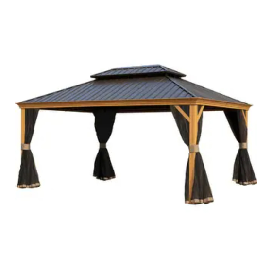
- Page 1 10’x12’ Apollo Hardtop Gazebo With Double Roof Assembly Manual Kozyard LLC Products www.kozyard.com © Copyright 2016 - 2023 Kozyard LLC. | All Rights Reserved. Version:20231006...
-
Page 2: Warnings And Cautions
Warnings and Cautions • Please read and follow this assembly and operation guide to reduce the risk of personal injury and damage to your gazebo. • Do not discard any of the packaging until you have checked that you have all the parts in place. The maximum weight capacity of this gazebo roof is 2500 pounds. - Page 3 Attn: Prior to assembly, verify all parts and and pieces are included to ensure an efficient installation process. BOX 1 B1 x2 G x4 B2 x2 H1 x4 B61 x2 H2 x1 B62 x2 H3 x1 C1 x2 R x8 C2 x2 C61 x2 S x104+2...
- Page 4 BOX 2 A x4 ITEM DESCRIPTION R2 x8 Pole Corner bracket #8 x16+2 Screws 16+2 M5x15 BOX 3 #6 x8+1 B x2 #7 x28+2 B6 x2 #9 x24+2 C x2 #10 x4+1 C6 x2 P1 x2 #11 x8+1 Q2 x4 Allen key L x4 Wrench...
- Page 5 BOX 4 Y1 x2 K x1 Y2 x2 K1 x1 ITEM DESCRIPTION Inside Roof Connector P x2 Outside Roof Connector Finishing Bar Union Bar Mosquito Net F x4 Mosquito Net BOX 5 V1 x2 V2 x2 W1 x2 W2 x2 W3 x2 W4 x2 W5 x2...
- Page 6 Step 1: Set up Poles Parts Required: Set up Poles (Part A) with Bracket (Part R2) and Stand Plates (Part L) using screws #8 and #1 as shown in the diagram. 8 x16 1 x12 (Inclined Plane) L x4 A x4 Reference for anchoring gazebo: •...
- Page 7 Parts Required: C x2 F x4 B x2 C6 x2 B6 x2 Step 2: Connect the Beams 1. Connect Beams (Part C and B) into one beam using Union Bar (Part F) with screws 1# as shown in the diagram. Short Beam Overall: 2.
- Page 8 Parts Required: B1 x2 C1 x2 B2 x2 C2 x2 C61 x2 B61 x2 C62 x2 B62 x2 STEP 3: Connect Joint Bars and Tracks with Beams 1. Connect Joint Bars (part C1,C61) and Tracks (Part C2,C62) to Beams (Part C ,C6) using #1 screws as shown in the diagram.
- Page 9 Parts Required: STEP 4: Set up Poles and Beams Use screws #3 first, then use screw #2 to connect Poles and Beams together as shown in the diagram. Tip: Place parts on carpet or rug to avoid scratches during assembly. Tip: 3 people suggested for this step.
- Page 10 Parts Required: J1 x4 J2 x4 STEP 5: Connect Solidifying Bars with Beams and Poles Affix the frame with Corner Solidifying Bars (Parts J1, J2) using #1 screws as shown in the diagram. Tip: Measure (DIAGONALLY) from posts to posts to assure alignment so all materials fit as planned.
- Page 11 Parts Required: H x4 G x4 STEP 6: Cover the connections 1. Finish Connecting Beams using Corner 2. Affix middle beams using Joint Covers (Part G) and #9 screws as Covers (Part H) with #9 screws as shown in diagram. shown in diagram.
- Page 12 Parts Required: H2 x1 STEP 7: Seal seams 1. After finishing Step 6, apply silicone rubber to the seams to ensure they're watertight. 2. If the screws are correctly attached through Spacer part S on the roof panels, sealing the cap screws with silicone rubber isn't necessary.
- Page 13 Parts Required: #4 x52 H1 x4 STEP 8: Install Hooks After finishing Hooks (Part #4) into the tracks, then put Joint Cover (Part H1) to lock them. Note the amount of hooks for each slot as noted below: Hooks into each slot of Hooks into each slot of Sidewall Track (part C2 , B2).
- Page 14 Parts Required: M x4 K x1 Step 9: Set up Corner Roof Bar Connect the inside Roof Connector (Part K) Attach Corner Roof Bar (Part M) to with the Corner Roof Bar (Part M) Poles (Part A ) using #1 screws as shown using #1 screws.
- Page 15 Parts Required: N x4 Step 10: Set up Roof Bar 1. Connect Roof Bar (Part N) to Inside Roof 2. Attach Roof Bar (Part N) to Beams using Connector (Part K)using #1 screws as #1 screws as shown in diagram. shown in diagram.
- Page 16 Parts Required: P x2 R x4 Q x2 Step 11: Set up Finishing Bar Attach Finishing Bar (Part P, Q) with Finish End (Part R) using #1 screws to Corner Roof Bar (Part M) as shown in the diagram. Upward View 10’x12’...
- Page 17 Parts Required: H3 x1 STEP 12:Snap Brackets Snap Bracket (Part Z, Z1, Z2) to roof panel edges as shown in the diagram. (with snaps facing upwards) Tips: 1. Wearing protective gloves is recommended. 2. To prevent Z-Clips (plastic brackets) from sliding off prior to assembly, apply double-sided adhesive tape (Part H3) to the underside (bottom) edge of the roof panels where the brackets (Part Z, Z1, Z2) are supposed to attach.
- Page 18 Parts Required: T x2 R x4 T1 x2 STEP 13: Assemble Roof Panels 1. Insert Roof Panels (Part v1, v2, v3, v4, v5, v6) to upper roof as shown in diagram. 2. Attach Finishing Bars (Part T, T1) to upper roof with Finish End (Part R) using #1 screws as shown in diagram.
- Page 19 Parts Required: K1 x1 STEP 14: Connect Outside Roof Connector Connect Outside Roof Connector (Part K1) to Inside Roof (Part K) using #1 screws as shown in the diagram. Upward View 10’x12’ assembly manual page 17...
- Page 20 Parts Required: U0 x4 U x4 U4 x4 U3 x4 STEP 15: Connect Solidifying Bars Attach Solidifying Bars ( Part U0,U) to roof bar or corner roof bar using Iron Angle (Part U3, U4) and #1 screws as shown in the diagram. 是...
- Page 21 Parts Required: Z x24 Z3 x2 H3 x1 Z4 x2 STEP 16: Snap Brackets (with snaps facing upwards) Tips: 1. Wearing protective gloves is recommended. 2. To prevent Z-Clips (plastic brackets) from sliding off prior to assembly, apply double-sided adhesive tape (Part H3) to the underside (bottom) edge of the roof panels where the brackets (Part Z, Z3, Z4) are supposed to attach.
- Page 22 Parts Required: Z x24 Z3 x2 Z4 x2 H3 x1 STEP 17: Snap Brackets Snap Bracket (Part Z, Z3, Z4) to the roof panel edges as shown in the diagram. (with snaps facing upwards) Tips: 1. Wearing protective gloves is recommended. 2.
- Page 23 Overall roof assembly: Please place the panels on the frame and assemble them from the centerline (Part N) to the left and right. Connect roof as pictured: Tip: Wearing protective gloves is recommended. Tips: To facilitate the easy fastening of roof panels (Part W3, Part X4), please use double-sided adhe- sive tape (Part H3) to affix Part S onto Panel (Part W3, Part X4) in advance.
- Page 24 Parts Required: S x104 L 45mm L 50mm L 28mm L 25mm STEP 18: Affix roof panels using screws and Spacers (Part S) as shown in diagram. Align all roof panels and screws LOOSELY (DO NOT TIGHTEN ANY SCREWS) until all the roof panels are aligned accordingly, THEN TIGHTEN all screws to secure the roof panels in place.
- Page 25 Parts Required: Q2 x4 P1 x2 STEP 19: Assemble Net Frame Attach Net Frames (Part P1,Q2) to Finishing Bars (Part P, Q) using #1 & #11 screws as shown in diagram. Upward View Perspective: Tips: The perspective drawing is for demonstrating how to assemble the final step that sets up the Net Frame (Parts P1, Q2) more effectively.
- Page 26 Solid Sidewalls on the outer rails as shown in the diagram. Y1,Y2 9 10 The privacy curtain is not included, but available for separate purchase. Visit kozyard.com and search for KZAHG1012SW to buy it. 13th 13th S1 x2 S2 x2 10’x12’...
-
Page 27: Care And Warranty
However, the privacy curtain and mosquito netting are warranted for just 90 days. For a comprehensive warranty policy, please visit www.kozyard.com. Be aware that warranty terms can change without prior notification. - Page 28 Don't hesitate to contact us directly if you are missing parts or need a replacement. Kozyard LLC © Copyright 2016 - 2023 Kozyard LLC. | All Rights Reserved.
Need help?
Do you have a question about the Apollo and is the answer not in the manual?
Questions and answers