Table of Contents
Advertisement
Quick Links
Advertisement
Table of Contents

Related Manuals for IBASE Technology SI-61S


Summary of Contents for IBASE Technology SI-61S
- Page 1 SI-61S Digital Signage Player User’s Manual Version 1.1 (Nov. 2018)
- Page 2 No part of this publication may be reproduced, copied, stored in a retrieval system, translated into any language or transmitted in any form or by any means, electronic, mechanical, photocopying, or otherwise, without the prior written consent of IBASE Technology, Inc. (hereinafter referred to as “IBASE”).
-
Page 3: Compliance
0.1% by weight (1000 ppm) except for cadmium, limited to 0.01% by weight (100 ppm). • Lead (Pb) • Mercury (Hg) • Cadmium (Cd) • Hexavalent chromium (Cr6+) • Polybrominated biphenyls (PBB) • Polybrominated diphenyl ether (PBDE) SI-61S User Manual... -
Page 4: Important Safety Information
CAUTION There is a danger of explosion if the lithium-ion battery is replaced with an incorrect battery. Replace only with the same or equivalent type recommended by the manufacturer. Dispose of used batteries by observing local regulations. SI-61S User Manual... -
Page 5: Warranty Policy
The arrangement of the peripherals • Software used (such as OS and application software) 3. If repair service is required, please download the RMA form at http://www.ibase.com.tw/english/Supports/RMAService/. Fill out the form and contact your distributor or sales representative. SI-61S User Manual... -
Page 6: Table Of Contents
COM1 and COM2 Serial Ports (CN1) ........17 2.5.2 ATX 12V Power Connector (J2) ........... 18 2.5.3 ATX Power Supply Connector (J5) ........18 2.5.4 Digital I/O Connector (J7) ............. 19 2.5.5 ACPI Status LED (J11) ............19 SI-61S User Manual... - Page 7 CSM Configuration ..............47 4.4.10 USB Configuration ..............48 Chipset Settings ..................49 4.5.1 System Agent Bridge Name ............ 49 4.5.2 PCH-IO Configuration ............. 51 Security Settings ................... 53 Boot Settings..................54 Save & Exit Settings................55 SI-61S User Manual...
- Page 8 Matrox C900 Graphics Card Installation ..........67 Video Walls Configuration for Matrox C900 Graphics Card ....70 Single-Card Configuration ............70 Dual-Card Configuration ............71 I/O Port Address Map ................72 Interrupt Request Lines (IRQ) ............... 75 Watchdog Timer Configuration .............. 77 viii SI-61S User Manual...
-
Page 9: Chapter 1 General Information
Chapter 1 General Information The information provided in this chapter includes: • Features • Packing List • Specifications • Optional Accessories • Overview • Dimensions... -
Page 10: Introduction
1.1 Introduction ® The SI-61S is powered by Intel Gen. desktop processors and supports three display outputs for HDMI, DVI-D and DisplayPort high definition video playback as well as iSmart energy-saving features such as power on/off scheduling and power resume function. It comes with a standard system bracket and measures 436 x 93 x 345 mm. -
Page 11: Packing List
General Information 1.3 Packing List If you buy a barebone SI-61S, your product package should include the items listed below. If any of the items below is missing, contact the distributor or the dealer from whom you have purchased the product. - Page 12 Operating: 0°C ~ 45°C (32°F ~ 113°F) Temperature • Storage: -20°C ~ 80°C (-4°F ~ 176°F) Relative 10 ~ 90% (non-condensing) Humidity Vibration mSATA: 5 grms, 5 ~ 500 Hz, random operation Protection All specifications are subject to change without prior notice. SI-61S User Manual...
-
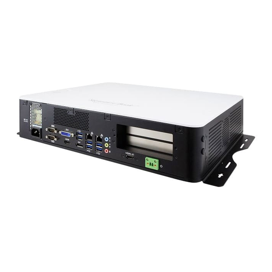
Page 13: Overview
General Information 1.5 Overview Top View Front View No. Name No. Name Power Button GPIO 4-In & 4-Out Port LED Indicators for Power & DC-In 12V Connector USB 2.0 Ports Reset Button SI-61S User Manual... - Page 14 2-Pin Terminal Block DVI-D Port (For remote power button) Expansion Slots for PCIe (x16) or HDMI Output PCIe (x8) DisplayPort Antenna Holes USB 3.0 Ports Mounting Kit Audio Jacks (From top to buttom: Line- In, Line-Out, Mic-In) SI-61S User Manual...
-
Page 15: Dimensions
General Information 1.6 Dimensions Unit: mm SI-61S User Manual... -
Page 16: Hardware Installation & Motherboard Information
Chapter 2 Hardware Installation & Motherboard Information This section contains general information about: • Installations • Jumper and connectors... -
Page 17: Installations
3. Gently push the module in an upright position unitl the ejector tabs of the memory slot close to hold the module in place when the module touches the bottom of the slot. To remove the module, press the ejector tabs outwards with your fintertips to eject the module. SI-61S User Manual... -
Page 18: Mini-Pcie Card Installation
1. Fasten the hex nut and the washer. 2. Apply adhesive around here. Then install the antenna. Info: The diameter of the nut is around 6.35 mm (0.25”-36UNC). SI-61S User Manual... -
Page 19: Mounting Installation
1. Turn your device upside down. Attach the wall-mount kit to the device and secure with the supplied 8 screws. 2. Prepare at least 4 screws (M3) to install the device on the wall as shown. 2.1.5 Pin Assignment for Power Input Connector Signal Signal Ground PWR_SW SI-61S User Manual... -
Page 20: Setting The Jumpers
2.2 Setting the Jumpers Configure your SI-61S by using jumpers to enable the features that you need based on your applications. Contact your supplier if you have doubts about the best configuration for your use. 2.2.1 How to Set Jumpers Jumpers are short-length conductors consisting of several metal pins with a base mounted on the circuit board. -
Page 21: Jumper & Connector Locations On Motherboard
Motherboard Information 2.3 Jumper & Connector Locations on Motherboard Motherboard: MI991AF SI-61S User Manual... -
Page 22: Jumpers Quick Reference
PCIe (x16) Mode Selection JP1, JP2 Factory Use Only 2.4.1 Clearing CMOS Data (JBAT1) Function Pin closed Illustration Normal (default) Clear CMOS 2.4.2 Clearing RTC Content (JBAT2) Function Pin closed Illustration Normal (default) Open Clear RTC Close SI-61S User Manual... -
Page 23: Pcie (X16) Mode Selection (Jp1, Jp2)
Motherboard Information 2.4.3 PCIe (x16) Mode Selection (JP1, JP2) Function Pin closed Illustration 1 x 16 JP1: Open (default) JP2: Open JP1: Open 2 x 8 JP2: Close JP1: Close 1 x 8, 2 x 4 JP2: Close SI-61S User Manual... -
Page 24: Connectors Quick Reference
GbE LAN & Two USB3.0 Ports CN6, CN9 SATA III Connectors CN7, CN8, CN10, CN11 HD Audio Connector CN12 PCIe (x16) Slot PCIE1 DDR4 SO-DIMM Slot J3, J4 Mini-PCIe Slot J9, J10 Factory Use Only J12, J13 SI-61S User Manual... -
Page 25: Com1 And Com2 Serial Ports (Cn1)
COM2 RS-232 port: Signal Name Signal Name DCD, Data carrier detect DSR, Data set ready RXD, Receive data RTS, Request to send TXD, Transmit data CTS, Clear to send DTR, Data terminal RI, Ring indicator ready Ground SI-61S User Manual... -
Page 26: Atx 12V Power Connector (J2)
ATX 12V Power Connector (J2) Signal Signal Ground +12V Ground +12V 2.5.3 ATX Power Supply Connector (J5) Signal Signal 3.3V 3.3V 3.3V -12V Ground Ground PS-ON Ground Ground Ground Ground Ground Power good 5VSB +12V +12V +3.3V Ground SI-61S User Manual... -
Page 27: Digital I/O Connector (J7)
Motherboard Information 2.5.4 Digital I/O Connector (J7) Signal Signal Ground OUT3 OUT1 OUT2 OUT0 2.5.5 ACPI Status LED (J11) Signal Signal +3VDUAL Ground +VCC3 Ground SI-61S User Manual... -
Page 28: Battery Connector (J14)
2.5.6 Battery Connector (J14) Signal Signal Battery+ Ground 2.5.7 USB 2.0 Connectors (J15) Signal Signal Ground Ground SI-61S User Manual... -
Page 29: Audio Pin Header For Chassis Front Panel (J16)
Audio Pin Header for Chassis Front Panel (J16) Signal Signal MIC IN_L Ground MIC IN_R LINE_R Sense Ground Sense LINE_L Sense Ground 2.5.9 COM3 & COM4 RS-232 Serial Ports (J17, J18) J18: J17: Signal Signal DCD# SOUT DTR# Ground DSR# RTS# CTS# SI-61S User Manual... -
Page 30: Front Panel Function Connector (J19)
2.5.10 Front Panel Function Connector (J19) Signal Signal Ground PWR_SW PWR_LED+ PWR_LED- (Ground) HDD_LED+ HDD_LED- Ground Reset 2.5.11 CPU Fan Power Connector (CPU_FAN1) Signal Signal Ground Rotation detection +12V Control SI-61S User Manual... -
Page 31: System Fan1 Power Connector (Sys_Fan1)
Motherboard Information 2.5.12 System Fan1 Power Connector (SYS_FAN1) Signal Signal Ground Rotation detection +12V Control SI-61S User Manual... -
Page 32: Chapter 3 Driver Installation
Chapter 3 Driver Installation The information provided in this chapter includes: • ® Intel Chipset Software Installation Utility • ® Intel HD Graphics Drivers • HD Audio Drivers • LAN Network Drivers • ® Intel Management Engine Components Drivers • ASMedia USB 3.1 Driver •... -
Page 33: Introduction
INF files for Plug & Play function for the chipset components. Follow the instructions below to complete the installation. 1. Run the Setup.exe file. ® 2. When the Welcome screen to the Intel Chipset Device Software appears, click Next to continue. SI-61S User Manual... - Page 34 3. Accept the license agreement and proceed with the installation process. 4. On the Readme File Information screen, click Install. 5. Installation is now complete. Restart the system for changes to take effect. SI-61S User Manual...
-
Page 35: Intel Hd Graphics Driver Installation
3. Click Yes to agree with the license agreement and continue the installation. 4. On the Readme File Information and Setup Progress screen, click Next and then Install. 5. Installation is now complete. Restart the system for changes to take effect. SI-61S User Manual... -
Page 36: Hd Audio Driver Installation
1. Run the Setup.exe file and the wizard starts. 2. On the Welcome screen of the InstallShield Wizard, click Next to start installing the audio driver on your system. 3. Installation is now complete. Restart the system for changes to take effect. SI-61S User Manual... -
Page 37: Lan Network Driver Installation
3.5 LAN Network Driver Installation 1. Run the Setup.exe file. 2. Click Install Drivers and Software. 3. On the Welcome screen of the InstallShield Wizard, click Next to continue. 4. Accept the license agreement and click Next. SI-61S User Manual... - Page 38 5. On the Setup Options screen, tick the checkbox to select the desired driver(s) and click Next. 6. Click Install. 7. Installation is now complete. Restart the system for changes to take effect. SI-61S User Manual...
-
Page 39: Intel Management Engine Components Drivers Installation
Installation 1. Run the Setup.exe file. 2. When the Welcome screen appears, click Next. 3. Accept the license agreement and click Next for installation. 4. Installation is now complete. Restart the system for changes to take effect. SI-61S User Manual... -
Page 40: Asmedia Usb 3.1 Drivers Installation
2. On the Welcome screen of the InstallShield Wizard, click Next to continue. 3. Accept the license agreement and click Next. 4. Click Install. 5. Installation is now complete. Restart the system for changes to take effect. SI-61S User Manual... -
Page 41: Fintek 8150X Serial Port Drivers Installation
3.8 Fintek 8150x Serial Port Drivers Installation 1. Run the Setup.exe file. 2. On the Welcome screen of the installer, click Next to continue. 3. Click Install. 4. Installation is now complete. Restart the system for changes to take effect. SI-61S User Manual... -
Page 42: Chapter 4 Bios Setup
Chapter 4 BIOS Setup This chapter describes the different settings available in the AMI BIOS that comes with the board. The topics covered in this chapter are as follows: • Main Settings • Advanced Settings • Chipset Settings • Security Settings •... -
Page 43: Introduction
These defaults have been carefully chosen by both AMI and your system manufacturer to provide the absolute maximum performance and reliability. Changing the defaults could make the system unstable and crash in some cases. SI-61S User Manual... -
Page 44: Main Settings
4.3 Main Settings BIOS Setting Description System Date Sets the date. Use the <Tab> key to switch between the data elements. System Time Set the time. Use the <Tab> key to switch between the data elements. SI-61S User Manual... -
Page 45: Advanced Settings
BIOS Setup 4.4 Advanced Settings This section allows you to configure, improve your system and allows you to set up some system features according to your preference. SI-61S User Manual... -
Page 46: Cpu Configuration
Options: A11, 1, 2, 3 Enables / Disables Advanced Encryption Standard). Intel Trusted Execution Enables utilization of additional hardware Tecnology capabilities provided by Intel(R) Trusted Execution Technology. Changes require a full power cycle to take effect. SI-61S User Manual... -
Page 47: Power & Performance
Technology support. Enabling will expose the CPPC v2 interface to allow for hardware controlled P-states. Turbo Mode Enables / Disables processor Turbo Mode (requires EMTTM enabled too). “Auto” means enabled, unless max. turbo ratio is bigger than 16 – SKL A0 W/A. SI-61S User Manual... -
Page 48: Pch-Fw Configuration
PCH-FW Configuration BIOS Setting Description AMT BIOS Features When disabled AMT BIOS features are no longer supported and user is no longer able to access MEBx Setup. Note: This option does not disable mamageability feature in FW. SI-61S User Manual... -
Page 49: Trusted Computing
BIOS Setup 4.4.4 Trusted Computing BIOS Setting Description Security Device Support Enables / Disables BIOS support for security device. O.S. will not show the security device. TCG EFI protocol and INT1A interface will not be available. SI-61S User Manual... -
Page 50: Acpi Settings
(OS/S4 sleep state). This option may not be effective with some operating systems. ACPI Sleep State Select the highest ACPI sleep state the system will enter when the SUSPEND button is pressed. Options: Suspend Disabled, S3 (Suspend to RAM) SI-61S User Manual... -
Page 51: Ismart Controller
For example, if setting up a schedule from Wednesday 5 p.m. to Thursday 2 a.m., configure two schedule slots. But if setting up a schedule from 3 p.m to 5 p.m. on Wednesday, configure only a schedule slot. SI-61S User Manual... -
Page 52: F81846 Super Io Configuration
4.4.7 F81846 Super IO Configuration BIOS Setting Description Serial Port Configuration Sets parameters of Serial Ports. Enables / Disables the serial port and select an optimal setting for the Super IO device. SI-61S User Manual... - Page 53 IO = 3E8h; IRQ = 3, 4, 5, 6, 7, 9, 10, 11, 12 • IO = 2E8h; IRQ = 3, 4, 5, 6, 7, 9, 10, 11, 12 F81846 Serial Port1 Mode F81846 serial port 1 mode selection: RS232, Selection RS422, RS485 modes. SI-61S User Manual...
-
Page 54: Hardware Monitor
The values are read-only values as monitored by the system and show the PC health status. CPU Shutdown This field enables or disables the Shutdown Temperature Temperature Options: Disabled, 70°C, 75°C, 80°C, 85°C, 90°C, 95°C SI-61S User Manual... -
Page 55: Csm Configuration
BIOS Setup 4.4.9 CSM Configuration BIOS Setting Description Network Controls the execution of UEFI and Legacy PXE OpROM. SI-61S User Manual... -
Page 56: Usb Configuration
The maximum time the device will take before it properly reports itself to the Host Controller. “Auto” uses default value for a Root port it is 100ms. But for a Hub port, the delay is taken from Hub descriptor. SI-61S User Manual... -
Page 57: Chipset Settings
BIOS Setup 4.5 Chipset Settings BIOS Setting Description System Agent (SA) System Agent parameters Configuration PCH-IO Configuration PCH parameters 4.5.1 System Agent Bridge Name BIOS Setting Description Graphics Configuration Configures the Graphics VT-d Enables / Disables VT-d capability. SI-61S User Manual... - Page 58 16M, 20M, 24M, 28M, 32M, 32M/F7, 36M, 40M, 44M, 48M, 52M, 56M, 60M) used by the internal graphics device DVMT Total Gfx Mem Selects DVMT5.0 total graphics memory size (256M, 128M, Max) used by the internal graphics device. SI-61S User Manual...
-
Page 59: Pch-Io Configuration
BIOS Setup 4.5.2 PCH-IO Configuration BIOS Setting Description SATA and RST SATA device options settings. Configuration PCM LAN Controller Enables / Disables onboard NIC. Wake on LAN Enable Enables / Disables integrated LAN to wake the system. SI-61S User Manual... - Page 60 Description SATA Controller(s) Enables / Disables SATA device. SATA Mode Selection Determines how SATA controller(s) operate. Options: AHCI, Intel RST Premium Serial ATA Ports Enables / Disables serial ports. Hot Plug Designates this port as hot pluggable. SI-61S User Manual...
-
Page 61: Security Settings
BIOS Setup 4.6 Security Settings BIOS Setting Description Administrator Password Sets an administrator password for the setup utility. User Password Sets a user password. SI-61S User Manual... -
Page 62: Boot Settings
Selects a Boot mode. Boot Option Priorities Sets the system boot order priorities for hard disk, CD/DVD, USB, Network. Hard Disk Drive BBS Number of seconds to wait for setup activation Priorities key. 65535 (0xFFFF) means indefinite waiting. SI-61S User Manual... -
Page 63: Save & Exit Settings
Restore Defaults Restores / Loads defaults values for all the setup options. Save as User Defaults Saves the changes done so far as user defaults. Restores the user defaults to all the setup Restore User Defaults options. SI-61S User Manual... -
Page 64: Appendix
Appendix This section provides the mapping addresses of peripheral devices and the sample code of watchdog timer configuration. • AMD Eyefinity Multiple Displays • Matrox C900 Graphics Card Installation • Video Walls Configuration for Matrox C900 Graphics Card • I/O Port Address Map •... -
Page 65: Amd Eyefinity Multiple Displays Configuration
Appendix AMD Eyefinity Multiple Displays Configuration AMD Eyefinity is applicable to SI-61S; it is a technology that allows two or more displays to be grouped together to form a single large desktop. Once AMD Eyefinity is configured, the final resolution is the horizontal and/or vertical sum of the individual monitors. - Page 66 However, this feature is not supported. Do not confuse with Try Advanced Setup (see below picture), which becomes available after Eyefinity Quick Setup is complete. The Try Advanced Setup option is used to customize the Eyefinity Display Group created after Eyefinity Quick Setup is complete. SI-61S User Manual...
- Page 67 Eyefinity Display Group. Refer to A.2 Customizing AMD Eyefinity Using Try Advanced Setup for details. Arrange Displays after Eyefinity Quick Setup To arrange displays in desired positions (optional): 1. Click Arrange Displays after Eyefinity Quick Setup is complete. SI-61S User Manual...
- Page 68 (i.e. Eyefinity Display Group + Extended Desktop Displays). In this example, physically connect 3 of the 4 displays first and arrange them in 3 x 1 extended desktop in the Operating System’s display settings. SI-61S User Manual...
-
Page 69: Customizing Amd Eyefinity Using Try Advanced Setup
Eyefinity Display Group or in one preferred display. By default, the Taskbar extends across all displays in a single row AMD Eyefinity Display Group. In a multi-row AMD Eyefinity Display Group, it extends across the bottom row of displays. SI-61S User Manual... - Page 70 4. To move the Taskbar, simply drag and drop it to the desired display. Ensure that the Taskbar setting is not set to “locked”. 5. To have the Taskbar running across multiple displays again, uncheck the Position the Windows taskbar on a single display option and click Continue. SI-61S User Manual...
- Page 71 Desktop option changes how the desktop image is shown across the displays by resizing it. To resize the desktop: 1. Click Try Advanced Setup (under Eyefinity tab in AMD Radeon Settings) after Eyefinity Quick Setup is complete. 2. Click Resize Desktop once Radeon Additional Settings launches. SI-61S User Manual...
- Page 72 Eyefinity Quick Setup is complete. 2. Click Adjust Bezel Compensation once Radeon Additional Settings launches. 3. Use the Chevrons (arrow heads) to move the triangle test pattern until it is properly aligned (as shown in below picture). SI-61S User Manual...
- Page 73 To customize Eyefinity desktop resolution: 1. Click Try Advanced Setup (under Eyefinity tab in AMD Radeon Settings) after Eyefinity Quick Setup is complete. 2. Click Customize Eyefinity Desktop Resolution once Radeon Additional Settings launches. SI-61S User Manual...
- Page 74 4. Select the preferred resolution from the Custom Resolution drop-down menu, and click Apply to save the setting. Open the Operating System’s display settings menu to change the resolution to the Custom Resolution selected in Step #4. SI-61S User Manual...
-
Page 75: Matrox C900 Graphics Card Installation
Appendix B. Matrox C900 Graphics Card Installation To install the Matrox C900 graphics card(s) to SI-61S, follow the instructions below. 1. Remove the 4 screws from the SI-61S cover. 2. Push down and open the SI-61S cover. 3. Remove the cables below from the cover. - Page 76 7. Install the 2 card to the upper slot by carefully holding it and fasten the screw to fix it. 8. Install the graphics card holer bracket which you removed at Step 6 and secure it with two screws. SI-61S User Manual...
- Page 77 If you use two graphics cards, you will need to connect a ribbon cable to both cards. 10. Install the hole plugs. 11. Restore the cables mentioned at Step 3 back to their original state. 12. Close the cover and push it upwards. 13. Fasten the 4 screws. SI-61S User Manual...
-
Page 78: Video Walls Configuration For Matrox C900 Graphics Card
Single-Card Configuration With a Matrox C900, you can create a display configuration of 9 screens as the most popular layouts below: 3 x 3 Landscape 3 x 3 Portrait 9 x 1 Landscape 1 x 9 Portrait SI-61S User Manual... -
Page 79: Dual-Card Configuration
The most popular dual-card configuration options are as follows. Please contact us if you can’t find the configuration you are looking for. 6 x 3 Landscape 6 x 3 Portrait 5 x 3 Landscape 5 x 3 Portrait SI-61S User Manual... -
Page 80: I/O Port Address Map
0x0000FFFF-0x0000FFFF Motherboard resources 0x00001800-0x000018FE Motherboard resources 0x0000164E-0x0000164F Motherboard resources 0x00000020-0x00000021 Programmable interrupt controller 0x00000024-0x00000025 Programmable interrupt controller 0x00000028-0x00000029 Programmable interrupt controller 0x0000002C-0x0000002D Programmable interrupt controller 0x00000030-0x00000031 Programmable interrupt controller 0x00000034-0x00000035 Programmable interrupt controller 0x00000038-0x00000039 Programmable interrupt controller SI-61S User Manual... - Page 81 Chipset SATA RAID Controller 0x0000F080-0x0000F083 Intel(R) Desktop/Workstation/Server Express Chipset SATA RAID Controller 0x0000F060-0x0000F07F Intel(R) Desktop/Workstation/Server Express Chipset SATA RAID Controller 0x00000000-0x00000CF7 PCI Express Root Complex 0x00000D00-0x0000FFFF PCI Express Root Complex 0x0000F0A0-0x0000F0A7 Intel(R) Active Management Technology - SOL (COM5) SI-61S User Manual...
- Page 82 Intel(R) HD Graphics 630 0x0000FF00-0x0000FFFE Motherboard resources 0x0000F040-0x0000F05F Intel(R) 100 Series/C230 Series Chipset Family SMBus - A123 0x00000060-0x00000060 Standard PS/2 Keyboard 0x00000064-0x00000064 Standard PS/2 Keyboard 0x0000D000-0x0000DFFF Intel(R) 100 Series/C230 Series Chipset Family PCI Express Root Port #7 - A116 SI-61S User Manual...
-
Page 83: Interrupt Request Lines (Irq)
Intel(R) Active Management Technology - SOL (COM5) IRQ 4294967281 Intel(R) Management Engine Interface IRQ 8 System CMOS/real time clock IRQ 4294967289 Intel(R) USB 3.0 eXtensible Host Controller - 1.0 (Microsoft) IRQ 11 Intel(R) 100 Series/C230 Series Chipset Family SMBus - A123 SI-61S User Manual... - Page 84 IRQ 12 Microsoft PS/2 Mouse IRQ 4294967292 Intel(R) 100 Series/C230 Series Chipset Family PCI Express Root Port #7 - A116 IRQ 4294967288 Realtek 8821AE Wireless LAN 802.11ac PCI-E IRQ 16 High Definition Audio Controller IRQ 16 MZ0380 PCI SI-61S User Manual...
-
Page 85: Watchdog Timer Configuration
**endptr; char SIO; printf("Fintek 81846 watch dog program\n"); SIO = Init_F81846(); if (SIO == 0) printf("Can not detect Fintek 81846, program abort.\n"); return(1); }//if (SIO == 0) if (argc != 2) printf(" Parameter incorrect!!\n"); return (1); SI-61S User Manual... - Page 86 //start counting //--------------------------------------------------------------------------- void DisableWDT(void) unsigned char bBuf; Set_F81846_LD(0x07); //switch to logic device 7 bBuf = Get_F81846_Reg(0xFA); bBuf &= ~0x01; Set_F81846_Reg(0xFA, bBuf); //disable WDTO output bBuf = Get_F81846_Reg(0xF5); bBuf &= ~0x20; bBuf |= 0x40; Set_F81846_Reg(0xF5, bBuf); //disable WDT SI-61S User Manual...
- Page 87 F81846_BASE = 0x2E; result = F81846_BASE; ucDid = Get_F81846_Reg(0x20); if (ucDid == 0x07) //Fintek 81846 goto Init_Finish; } F81846_BASE = 0x00; result = F81846_BASE; Init_Finish: return (result); //--------------------------------------------------------------------------- void Unlock_F81846 (void) outportb(F81846_INDEX_PORT, F81846_UNLOCK); outportb(F81846_INDEX_PORT, F81846_UNLOCK); //--------------------------------------------------------------------------- void Lock_F81846 (void) SI-61S User Manual...
- Page 88 // KIND, EITHER EXPRESSED OR IMPLIED, INCLUDING BUT NOT LIMITED TO THE // IMPLIED WARRANTIES OF MERCHANTABILITY AND/OR FITNESS FOR A PARTICULAR // PURPOSE. //--------------------------------------------------------------------------- #ifndef F81846_H #define F81846_H //--------------------------------------------------------------------------- #defineF81846_INDEX_PORT (F81846_BASE) #defineF81846_DATA_PORT (F81846_BASE+1) //--------------------------------------------------------------------------- #defineF81846_REG_LD 0x07 //--------------------------------------------------------------------------- #define F81846_UNLOCK 0x87 #defineF81846_LOCK 0xAA //--------------------------------------------------------------------------- SI-61S User Manual...
- Page 89 Appendix unsigned int Init_F81846(void); void Set_F81846_LD( unsigned char); void Set_F81846_Reg( unsigned char, unsigned char); unsigned char Get_F81846_Reg( unsigned char); //--------------------------------------------------------------------------- #endif // F81846_H SI-61S User Manual...
Need help?
Do you have a question about the SI-61S and is the answer not in the manual?
Questions and answers