
Related Manuals for AgileX TITAN


Summary of Contents for AgileX TITAN
- Page 1 TITAN User Manual TITAN AgileX Robotics Team V.2.0.1 2023.08 册 Document version Version Date Edited by Reviewer Notes V1.0.0 2022/10/15 何士玉 first draft Update V2.0.0 2023/3/23 李圣望、何士玉 agreement content 1 / 4 9...
- Page 2 Any users of the TITAN should comply with laws and regulations of relevant countries and ensure that there are no obvious hazards in the application of the TITAN. This includes but is not limited to the following: Responsibility Do a risk assessment of the robotic system that uses the TITAN.
- Page 3 Ensure that the surrounding area is relatively open when operating the TITAN. Please do remote control within sight. The maximum load of the TITAN is 150 KG. Please ensure that the payload does not exceed 150 KG when using. When installing external equipment on the TITAN, Please ensure their centroid location is at the TITAN s center of rotation.
- Page 4 The batteries of TITAN products are not fully charged when they leave the factory. The specific battery voltage and power can be displayed through the voltage indicator at the rear of the TITAN chassis or through the vol and batt on the remote control.
- Page 5 If you have any questions about the use process, please follow the relevant instruction manual or consult relevant technical personnel Before using the equipment to operate, pay attention to the situation on site to avoid personnel safety problems caused by misoperation In case of emergency, power off...
-
Page 6: Table Of Contents
Document version Important Safety Information CONTENTS 1 Introduction to TITAN 1.1 Specifications 1.2 Required for Development 2 Basic Introduction 2.1 Status of the TITAN 2.2 Description of Electrical Interfaces 2.3 Remote Control Instructions 3 Usage and Development 3.1 Operation 3.2 CAN Communication Protocol 3.3 TITAN use manual for ROS 3.4 The Github ROS development kit and user manual 3.5 Firmware Upgrade... -
Page 7: Specifications
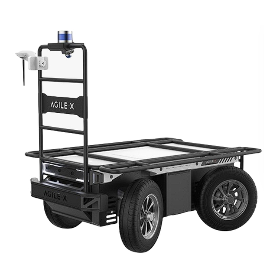
TITAN chassis, suitable for a variety of complex terrain. At the same time, it can be equipped with stereo cameras, lidar, GPS, IMU, manipulators and other equipment, and is applied to unmanned inspection, security, scientific research, exploration and logistics and other fields. -
Page 8: Required For Development
Collection and Transportation 1.2 Required for Development TITAN can be equipped with FS remote control when it leaves the factory. Users can control the chassis through the remote control to complete mode switching, movement and steering control. TITAN is equipped with a standard CAN communication interface, and users can carry out secondary development through the CAN interface. -
Page 9: Status Of The Titan
TITAN, which is convenient for users to carry external equipment for expansion. 2.1 Status of the TITAN The user can check the status of the TITAN through its CAN message. Please refer to Table 2.1 for specific status. Status Description... -
Page 10: Description Of Electrical Interfaces
At this time, the chassis will not move and accept external command control. Detailed Status Check by CAN message Information Table 2.1 Status Description Table for the TITAN 2.2 Description of Electrical Interfaces Figure 2.2 Back View of the TITAN 1 0 / 4 9... - Page 11 Therefore, users need to be aware that the TITAN chassis platform will issue a low voltage warning notification before reaching the critical voltage, and users should pay attention to charging during use. ...
-
Page 12: Remote Control Instructions
2.3 Remote Control Instructions Figure 2.4 Introduction of the remote control As shown in the diagram, the functions of the buttons are defined as follows: SWB is the control mode selection switch. When it is switched to the top position, it is in command control mode. When it is switched to the middle position, it is in remote control mode. SWA is the parking switch. -
Page 13: Usage And Development
After starting the TITAN mobile robot chassis normally, turn on the remote controller and switch SWB to remote control mode. This will allow you to control the movement of the TITAN platform using the remote controller. SWD is the off-road mode switch stick. When switched to the upper position, it is in normal mode. - Page 14 At this time, the power switch is released, and the TITAN is powered off. Power on and off The switch marked with "STOP" at the rear of the TITAN is an emergency stop switch. Pressing it will stop the TITAN immediately and turning it clockwise will exit the emergency stop mode. Charge Check the battery voltage.
-
Page 15: Can Communication Protocol
Start the TITAN normally, turn on the remote control, and then switch the SWB to the command control mode (move SWB to the top). At this time, the TITAN will accept commands from the CAN bus, and the host can also analyze the status of the TITAN using the feedbacked real-time data through the CAN bus. - Page 16 0x00 Standby mode 0x01 CAN Command control mode byte [1] Control mode unsigned int8 0x03 Remote control mode High order byte of battery byte [2] voltage unsigned int16 Actual voltage X 10 (the unit is 0.1 V) Low order byte of battery byte [3] voltage Highest order...
- Page 17 Byte Meaning Reserved, the default value is byte [4] Front steering encoder status bit [0] (0: no fault 1: fault) Rear steering encoder status bit [1] (0: no fault 1: fault) Reserved, the default value is bit [2] Reserved, the default value is byte [5] bit [3] Reserved, the default value is...
- Page 18 Reserved, the default value is bit [3] Reserved, the default value is bit [4] Reserved, the default value is bit [5] Over temperature protection bit [6] status (0: normal; 1: triggered) Over current protection bit [7] status (0: normal; 1: triggered) byte [7] Battery undervoltage status bit [0]...
- Page 19 Reserved, the default value is bit [7] The motion control feedback frame includes the current linear speed and steering angle of the vehicle. The details of the protocol are as follows Command Motion Control Feedback Command Node for Receive timeout Node for sending Period receiving (ms)
- Page 20 High order byte of steering angle byte [6] Actual steering angle X 100 (the unit signed int16 is 0.001 rad) byte [7] Low order byte of steering angle The motion control frame includes the linear speed control command and the steering angle control command. The details of the protocol are as follows: Command Control Command ...
- Page 21 CAN control mode. As shown in Figure 3.2.1, when TITAN is in this state, the feedback rotation angle is (α3+α4)/2, the negative value is the left turning direction, and the positive value is the right turning direction; the feedback speed is the average speed of the four wheels (ie Chassis movement line speed), the negative value is reverse, the positive value is forward.
- Page 22 3.2.1 TITAN structure The mode setting frame is used to set the terminal control interface, and the details of the protocol are as follows. Command Control Command Node for Receive timeout Node for sending Period receiving (ms) 2 2 / 4 9...
- Page 23 Decision-making Node for the 0x421 None None and control unit chassis Data length 0x01 Byte Meaning Data type Note 0x00 Standby mode 0x01 CAN command control mode byte [0] Control mode unsigned int8 Boot into standby mode by default Control mode description: when the chassis is powered on and the remote control is not connected, the control mode is standby mode.
- Page 24 0x00 Clear all non-critical faults 0x01~0x04 respectively correspond to clearing the communication failure of No. 1~4 motor drivers 0x09 Clear the battery undervoltage fault and try to restore the power supply Error clearing byte [0] unsigned int8 command 0x0a Clear remote control signal loss fault 0x0b~0x0c respectively correspond to clearing the faults of the front and...
- Page 25 Command CAN upgrade bus silent mode setting command Node for Receive timeout Node for sending Period receiving (ms) Decision-making Node for the 0x422 None None and control unit chassis Data length 0x01 Byte Meaning Data type Note 0x00 Exit CAN upgrade bus silent mode 0x01 Enter CAN upgrade bus silent mode ...
- Page 26 Data length 0x01 Byte Meaning Data type Note 0x00 Chassis exits off-road mode byte [0] Control mode unsigned int8 0x01 Chassis enters off-road mode Sample data, the following data is only for testing. byte [0] byte [1] byte [2] byte [3] byte [4] byte [5] byte [6]...
- Page 27 High order byte of motor The current speed of the motor, byte [0] speed signed int16 whose unit is RPM (Revolutions Per byte [1] Low order Minute) byte of motor speed High order byte of motor byte [2] current The present current of the motor, signed int16 whose unit is 0.1 A byte [3] Low order byte of motor...
- Page 28 High order byte [0] byte of driver voltage The current driver voltage, whose unsigned int16 unit is 0.1 V Low order byte [1] byte of driver voltage High order byte [2] byte of drive temperature signed int16 The unit is 1 ℃. Low order byte of byte [3] driver temperatur...
- Page 29 bit[4] Sensor status (0: Normal; 1: Abnormal) bit[5] Driver status (0: Normal; 1: Abnormal) bit[6] Drive enable status (0: disable; 1: enable) bit[7] Reserved Steering zero point setting and feedback commands are used to calibrate the zero point. The details of the protocol are as follows: Steering zero point setting command Command Steering zero point setting command...
- Page 30 Byte Meaning Data type Note Set the current 0xEE set the current position to Byte [0] position as the unsigned int8 zero point successfully zero point Steering angle feedback Command Information feedback frame of steering angle Node for Receive timeout Node for sending Period receiving (ms)
- Page 31 byte [6] Reserved 0X00 byte [7] Rotational speed feedback Due to the adoption of a drive axle in the chassis, the front wheel speed is actually the drive shaft speed, which can be understood as the average of the front left and front right wheel speeds. The same applies to the rear wheels.
- Page 32 byte [6] Reserved 0X00 byte [7] Odometer information feedback frame is as follows Command Odometer information feedback Node for Receive timeout Node for sending Period receiving (ms) Drive-by-wire Decision-making 0×311 20ms None chassis and control unit Data length 0x08 Byte Meaning Data type Note Front wheel odometer highest byte Front wheel...
- Page 33 Rear wheel odometer highest byte Rear wheel odometer byte [4] second highest Chassis rear wheel odometer byte [5] byte feedback, signed int32 byte [6] Rear wheel Unit: mm odometer byte [7] second lowest byte Rear wheel odometer lowest byte The remote control information feedback frame is as follows Command Remote control information feedback Node for...
- Page 34 bit[0-1]: SWA: 2-Upper gear, 3- Lower gear bit[2-3]: SWB: 2-Upper gear, 1- Middle gear, 3-Lower gear Remote control byte [0] unsigned int8 SW feedback bit[4-5]: SWC: 2-Upper gear, 1- Middle gear, 3-Lower gear bit[6-7]: SWD: 2-Upper gear, 3- Lower gear Right joystick byte [1] unsigned int8...
- Page 35 Drive-by-wire Decision-making 0x361 500ms None chassis and control unit Data length 0x08 Byte Meaning Data type Note Battery SOC byte [0] State of unsigned int8 Range 0~100 Charge Battery byte [1] SOH (State of unsigned int8 Range 0~100 Health) High order byte byte [2] of battery voltage unsigned int16...
- Page 36 Command The feedback data of BMS Node for Receive timeout Node for sending Period receiving (ms) Drive-by-wire Decision-making 0x362 500ms None chassis and control unit Data length 0x04 Byte Meaning Data type Note BIT1: Overvoltage; BIT2: Undervoltage; BIT3: High byte [0] Alarm Status 1 unsigned int8...
- Page 37 Decision- Drive-by-wire making and 0x363 500ms None chassis control unit Data length 0x08 Byte Meaning Data type Note byte [0] Battery SOC unsigned int8 Range 0~100 byte [1] Battery SOH unsigned int8 Range 0~100 High order byte byte [2] of battery voltage unsigned int16 Unit: 0.01 V byte [3]...
- Page 38 Decision- Drive-by-wire making and 0x364 500ms None chassis control unit Data length 0x04 Byte Meaning Data type Note BIT1: Overvoltage; BIT2: Undervoltage; BIT3: High byte [0] Alarm Status 1 unsigned int8 temperature; BIT4: Low temperature; BIT7: Discharge overcurrent byte [1] Alarm Status 2 unsigned int8 BIT0: Charging overcurrent...
- Page 39 Decision- Drive-by-wire making and 0x365 500ms None chassis control unit Data length 0x08 Byte Meaning Data type Note byte [0] Battery SOC unsigned int8 Range 0~100 byte [1] Battery SOH unsigned int8 Range 0~100 High order byte byte [2] of battery voltage unsigned int16 Unit: 0.01 V byte [3]...
-
Page 40: Titan Use Manual For Ros
BIT0: Charging overcurrent BIT1: Overvoltage; BIT2: Undervoltage; BIT3: High byte [2] Warning Status 1 unsigned int8 temperature; BIT4: Low temperature; BIT7: Discharge overcurrent byte [3] Warning Status 2 unsigned int8 BIT0: Charging overcurrent 3.3 TITAN use manual for ROS 4 0 / 4 9... - Page 41 ● Hardware Connection and Preparation Pull out the CAN wires of the circular connector on the rear of TITAN, and connect can_H and can_L wires of the CAN to the CAN_TO_USB adapter; power on the TITAN; connect the CAN_TO_USB adapter to the USB port of the laptop. The wiring diagram is shown in the figure below.
- Page 42 Install and use can-utils to test hardware sudo install can-utils ● If the CAN-TO-USB adapter has been connected to the TITAN and the TITAN has been powered on, the command below can be used to monitor the data from the TITAN. candump can0 4 2 / 4 9...
-
Page 43: The Github Ros Development Kit And User Manual
ROS communication architecture. TITAN_msgs Define the message format of the topic for TITAN status feedback TITAN_bringup The startup file of the TITAN node and the keyboard_control node, and the script to enable the USB_TO_CAN module Send commands to control the TITAN through the keyboard: 1. - Page 44 To facilitate users to upgrade the firmware of the 4WD chassis and bring customers a better experience, the TITAN chassis provides a hardware interface and a software for upgrading firmware. The GUI (Graphical User Interface) of the software is shown in the figure below.
- Page 45 3.Click the Load Firmware File button to load the firmware to be upgraded. If the loading is successful, the firmware information will be obtained, as shown in the figure 4.Click the node to be upgraded in the node list box, and then click Start Upgrade Firmware to start upgrading the firmware.
-
Page 46: The Vehicle Body Coordinate System
3.6 The vehicle body coordinate system 4 6 / 4 9... -
Page 47: 4 Maintenance Instructions
The vehicle body coordinate system is defined as follows: the center of the vehicle is the origin, the positive direction of the X-axis points to the front of the vehicle, the positive direction of the Y- axis points to the left side of the vehicle, and the positive direction of the Z-axis points upwards. 4 Maintenance Instructions 4.1 Maintenance method The vehicle maintenance... - Page 48 4 8 / 4 9...
- Page 49 4 9 / 4 9...
Need help?
Do you have a question about the TITAN and is the answer not in the manual?
Questions and answers