
Related Manuals for QSFPTEK S5310-48P6X


Summary of Contents for QSFPTEK S5310-48P6X
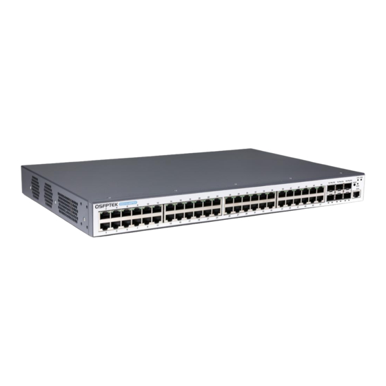
- Page 1 S5310-48P6X Quick Start Guide 48-Port Gigabit Ethernet L3 PoE+ Switch 48x PoE+ Ports@740w , with 6x 10GE SFP+ uplink, Support Stacking V1.0 www.qsfptek.com v1.0 1 / 10...
- Page 2 Gbps links with the aggregation layer switch. It supports stacking up to eight S5300 series switches, making them logically regarded as one for interconnection and management. We appreciate your decision to select S5310-48P6X. This manual is intended to help you become acquainted with the switch design a nd provide instructions for implementing the switches into your network.
-
Page 3: Hardware Overview
AC POWER2 Abbrev Name Description AC POWER1 AC power supply Input voltage: AC100~240V AC POWER2 AC power supply (Dual power backup) Input voltage: AC100~240V The grounding column The grounding column The grounding column must be fine. www.qsfptek.com v1.0 3 / 10... - Page 4 Mounting the Switch Connecting the Power 1. Plug the AC power cord to the switch power port on the back rear. 2. Connect the other end of the power cord to a AC power source equipment. www.qsfptek.com v1.0 4 / 10...
- Page 5 1. Insert the SFP+ module into the SFP+ port. 2. Plug a fiber patch cable to the SFP+ transceiver. 3. Connect the other end of the fiber to the device that you want to realize data communication. www.qsfptek.com v1.0 5 / 10...
-
Page 6: Connecting The Management Ports
2. Insert the RJ45 connector of the console cable into the console port on the switch. 3. Connect the D89 female connector on the other end of the console cable to the serial port on the computer host. www.qsfptek.com v1.0... -
Page 7: Configuring The Switch
Step 2: Set the IP address of the computer to 192.168.0.x (where "x" is any number from 2 to 254) and the subnet mask to 255.255.255.0. Step 3: Open a web browser and type http://192.168.0.2 in the address bar. Enter the default username and password (admin/admin). Step 4: Click sign-in to access the web-based configuration page. www.qsfptek.com v1.0 7 / 10... - Page 8 Step 3: Configure the parameters of the terminal emulation software as follows: 9600 bits per second, 8 data bits, no parity, 1 stop bit, and no flow control. Step 4: Enter the default username and password (admin/admin). www.qsfptek.com v1.0 8 / 10...
-
Page 9: Troubleshooting
If the CLI port does not work after the system is started up, check whether the CLI port is set to a baud rate of 9600 bps, eight data bits, no sum check bit, one stop bit and no traffic control. www.qsfptek.com v1.0... -
Page 10: Support And Other Resources
Product Warranty S5300 series switches are backed by a 5-year limited warranty supported by QSFPTEK. And you are eligible to apply for a return or e -xchange of your items within 14 days of receiving them. For more details about applying qualifications, please live chat or email sales@qsfptek.com...
Need help?
Do you have a question about the S5310-48P6X and is the answer not in the manual?
Questions and answers