
Related Manuals for QSFPTEK S5300-24P4X


Summary of Contents for QSFPTEK S5300-24P4X
- Page 1 S5300-24P4X Quick Start Guide 24-Port Gigabit Ethernet L2+ Switch 24x PoE+ Ports@370W, with 4x 10GE SFP+ Uplinks, Support Stacking V1.0 www.qsfptek.com v1.0 1 / 11...
-
Page 2: Hardware Overview
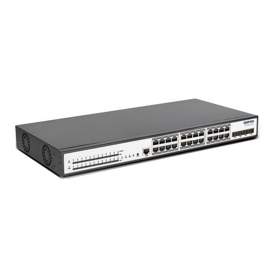
Introduction The QSFPTEK S5300-24P4X is a next-gen PoE+ switch, with 24x GE RJ45 and 4x 10GE SFP+ uplinks. The 24x RJ45 ports support IEEE802.3af/at, supports powering connected IP phones, wireless access points, or other standards-compliant PoE and PoE+ end-network devices. It supports stacking of up to two S5300 series switches to deliver redundancy, simple management and resilience of network capacity. - Page 3 If the switch is powered on, the PWR indicator is on. ACT LED LINK/ACT Back Panel Abbrev Name Description AC POWER AC power supply Input voltage: AC100~240V Power switch Power switch ON means the power is switched on, while www.qsfptek.com v1.0 3 / 11...
- Page 4 Put the machine box at the place where cool air can blow off the heat inside the machine box. Make sure the machine box is sealed because the opened machine box will reverse the cool air flow Mounting the Switch Connecting the Power www.qsfptek.com v1.0 4 / 11...
- Page 5 2. Connect the other end of the power cord to a AC power source equipment. Connecting the RJ45 Port 1. Connect one end of the Ethernet cable to the RJ45 port on networking equipment, such as PC, printer, server, storage, etc. www.qsfptek.com v1.0 5 / 11...
- Page 6 1. Insert the SFP+ module into the SFP+ port. 2. Plug a fiber patch cable to the SFP+ transceiver. 3. Connect the other end of the fiber to the device that you want to realize data communication. www.qsfptek.com v1.0 6 / 11...
-
Page 7: Connecting The Management Ports
Step 1: Connect your computer to the switch using an Ethernet cable and open a web browser. Step 2: Set the IP address of the computer to 192.168.0.x (where "x" is any number from 2 to 254) and the subnet mask to 255.255.255.0. www.qsfptek.com v1.0 7 / 11... - Page 8 Step 2: Launch the terminal simulation software such as Hyper Terminal on the computer. Step 3: Configure the parameters of the terminal emulation software as follows: 9600 bits per second, 8 data bits, no parity, 1 stop bit, and no flow control. www.qsfptek.com v1.0 8 / 11...
-
Page 9: Troubleshooting
Step 4: Enter the default username and password (admin/admin). Troubleshooting Hardware Fault Analysis Power and cooling systems—power and fan Port, cable and connection—ports on the front panel of the switch and the cables connecting these ports www.qsfptek.com v1.0 9 / 11... -
Page 10: Support And Other Resources
If the CLI port does not work after the system is started up, check whether the CLI port is set to a baud rate of 9600 bps, eight data bits, no sum check bit, one stop bit and no traffic control. Support and Other Resources Contact us https://www.qsfptek.com/company/contact-us.html Email sales@qsfptek.com ... -
Page 11: Product Warranty
Product Warranty S5300 series switches are backed by a 5-year limited warranty supported by QSFPTEK. And you are eligible to apply for a return or e -xchange of your items within 14 days of receiving them. For more details about applying qualifications, please live chat or email sales@qsfptek.com...
Need help?
Do you have a question about the S5300-24P4X and is the answer not in the manual?
Questions and answers