
Related Manuals for QSFPTEK S5300-24S8T6X


Summary of Contents for QSFPTEK S5300-24S8T6X
- Page 1 S5300-24S8T6X Quick Start Guide 24-Port Gigabit Ethernet L3 Switch 24x GE SFP and 8x GE RJ45 Ports, with 6x 10GE SFP+ Uplink, Support Stacking V1.0 www.qsfptek.com v1.0 1 / 10...
-
Page 2: Hardware Overview
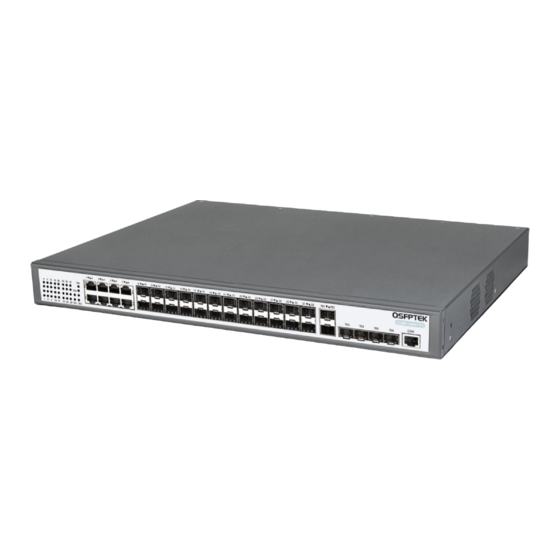
Introduction The S5300-24S8T6X is a next-gen fiber optic Ethernet switch, features 24x GE SFP and 8x GE RJ45 downlinks and 6x 10GE SFP+ uplinks. It supports stacking of up to eight switches, making them logically regarded as one switch for interconnection and management. - Page 3 Indicators for SFP ports TE1~TE6 Link/Act indicator on SFP+ ports Indicators for SFP+ ports Back Panel Abbrev Name Description Grounding column The grounding column The grounding column must be fine. POWER AC power supply Input voltage: AC100~240V www.qsfptek.com v1.0 3 / 10...
-
Page 4: Installation Requirements
Site Environment Make sure that the workshop is well-ventilated, the heat of electrical devices is well-discharged . Avoid to damage devices by following the electrostatic discharge prevention procedure. S5300-24S8T6X Hardware Installation Manual. Put the machine box at the place where cool air can blow off the heat inside the machine box. Make sure the machine box is ... - Page 5 Connecting the Power 1. Plug the AC power cord to the switch power port on the back rear. 2. Connect the other end of the power cord to a AC power source equipment. Connecting the RJ45 Ports www.qsfptek.com v1.0 5 / 10...
- Page 6 1. Connect SFP modules through the fiber to other Ethernet terminal devices. 2. Connect the other end of the cable to the SFP port on the front of the switch. Connecting the SFP+ Ports 1. Insert the SFP+ module into the SFP+ port. www.qsfptek.com v1.0 6 / 10...
-
Page 7: Connecting The Management Ports
3. Connect the D89 female connector on the other end of the console cable to the serial port on the computer host. Configuring the Switch Configuring the Switch Using the Web-based Interface Step 1: Connect your computer to the switch using an Ethernet cable and open a web browser. www.qsfptek.com v1.0 7 / 10... - Page 8 Step 2: Launch the terminal simulation software such as Hyper Terminal on the computer. Step 3: Configure the parameters of the terminal emulation software as follows: 9600 bits per second, 8 data bits, no parity, 1 stop bit, and no flow control. www.qsfptek.com v1.0 8 / 10...
-
Page 9: Troubleshooting
3. If the CLI port does not work after the system is started up, check whether the CLI port is set to a baud rate of 9600 bps, eight data bits, no sum check bit, one stop bit and no traffic control. www.qsfptek.com v1.0... -
Page 10: Support And Other Resources
Product Warranty S5300 series switches are backed by a 5-year limited warranty supported by QSFPTEK. And you are eligible to apply for a return or exchange of your items within 14 days of receiving them. For more details about applying qualifications, please live chat or email for support.
Need help?
Do you have a question about the S5300-24S8T6X and is the answer not in the manual?
Questions and answers