Advertisement
Quick Links
Advertisement

Related Manuals for Best Fitness BFHYP10R


Summary of Contents for Best Fitness BFHYP10R
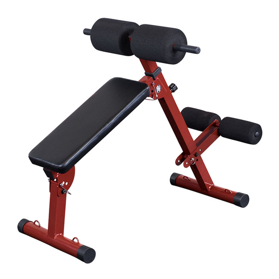
- Page 1 051616 BFHYP10R O w n e r ’ s M a n u a l...
- Page 2 BeFOre YOu Begin Thank you for purchasing the Best Fitness BFHYP10R. This gym is part of the Best Fitness quality strength training machines, which lets you target specific muscle groups to achieve better muscle tone and overall body conditioning. To maximize your use of the equipment please study this Owner’s Manual thoroughly.
-
Page 3: Important Safety Instructions
Forest Park, IL 60130 USA damaged the equipment. • Assemble and operate the BFHYP10R on a solid, level surface. Locate the unit a few feet from the walls or Retain this Owner’s Manual for future reference. -
Page 4: Safety Guidelines
saFetY guidelines Successful resistance training programs have one prominent feature in common...safety. Resistance training has some inherent dangers, as do all physical activities. The chance of injury can be greatly reduced or completely removed by using correct lifting techniques, proper breathing, maintaining equipment in good working condition, and by wearing the appropriate clothing. - Page 5 Assembly of the BFHYP10R takes professional installers about 1/2 hour to complete. If this is the first time you have assembled this type of equipment, plan on significantly more time. rofessional installers are highly recommended However, if you acquire the appropriate tools, obtain assistance, and follow the assembly steps sequentially, the process will take time, but is fairly easy.
- Page 6 s t e P Be careful to assemble all components in the sequence they are presented. Position the bench on it’s side. Unfold the BFHYP10 R by rotating Front Support Frame (1) and Rear Support Frame (2) outwards as shown in Diagram 1. If repeated adjustments and storage position is desired, install removable safety pins (25) as described in Diagram 2.
- Page 7 s t e P Above shows STEP 1 assembled and completed. Diagram 2 Diagram 1...
- Page 8 s t e P Be careful to assemble all components in the sequence they are presented. Position Ankle Roller Frame (4) as shown in the diagram and secure using: One 11 (M10x70 hex head bolt) Two 9 (M10 flat washer) One 10 (M10 nylon nut) NOTE: Adjust the position of Ankle Roller Frame (4), as necessary, depending on the user’s physical size.
- Page 9 s t e P Above shows STEP 2 assembled and completed.
- Page 10 Hardware (actual size shown)
-
Page 11: Hardware List
Hardware list PART# DESCRIPTION Front Support Frame Rear Support Frame Back Seat Frame Ankle Roller Frame Adjustable Upper Frame Upper Roller Bar Back Pad M10x75 Hex Head Bolt M10 Flat Washer M10 Nylon Nut M10x70 Hex Head Bolt M8x70 Hex Head Bolt M8 Flat Washer M60 End Cap M100x200 Foam Roller... -
Page 12: Exploded View Diagram
exPlOded View diagraM... - Page 14 1900 S. Des Plaines Ave. Forest Park, Il 60130 1 (800) 556-3113 Hours: M-F 8:30 - 5:00 CST www.BestFitness.com Copyright 2009. Body-Solid. All rights reserved. Body-Solid reserves the right to change design and specifications when we feel it will improve the product. Body-Solid machines maintain several patented and patent pending features and designs.
Need help?
Do you have a question about the BFHYP10R and is the answer not in the manual?
Questions and answers