Advertisement
Quick Links
Advertisement

Related Manuals for Best Fitness BFCCO10


Summary of Contents for Best Fitness BFCCO10
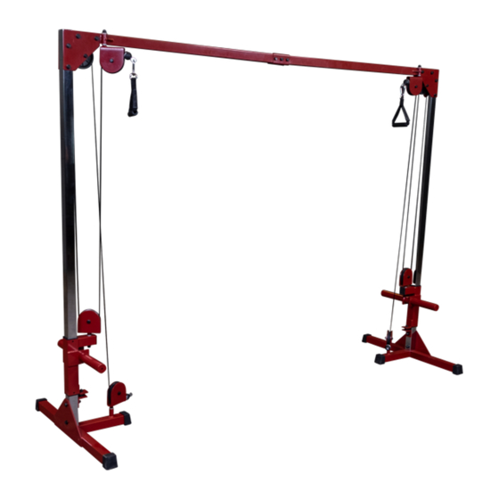
- Page 1 V. BFCCO10-20210310 BFCCO10 O w n e r ’ s M a n u a l...
- Page 2 It is recommended that you workout with a training partner. Do not allow children or minors to play on or around this equipment. If unsure of proper use of equipment, call your local Best Fitness distributor or the Best Fitness customer service center at 1-800-556-3113.
-
Page 3: Table Of Contents
taBle OF COntents • saFety instruCtiOns ......Page 4 • PreParatiOn ........... Page 5 • HarDware list ........Page 6 • HarDware illustratiOn ......Page 8 • asseMBly instruCtiOns ......Page 10 • eXPlODeD View ........Page 20 • COntaCt Page .. -
Page 4: Safety Instructions
Antes de comenzar cualquier programma de ejercicios, deberias tener un examen fisico con su doctor. When using exercise equipment, you The BFCCO10 is designed for your enjoyment. By should always take basic precautions, following these precautions and using common... -
Page 5: Preparation
PreParatiOn Thank you for purchasing the BFCCO10. This machine is part of the Best Fitness line of quality strength training machines, which lets you target specific muscle groups to achieve better muscle tone and overall body conditioning. To maximize your use of the equipment please study this Owner’s Manual thoroughly. -
Page 6: Hardware List
BFCCO10 - Part list Part# DesCriPtiOn Quantity uPrigHt 2 PCs. Base FraMe 2 PCs. l BraCKet 2 PCs. sliDing Carriage 2 PCs. Pulley BraCKet 4 PCs. MiD Pulley BraCKet 2 PCs. suPPOrt BraCKet 4 PCs. CrOssBeaM a 1 PCs. CrOssBeaM B 1 PCs. - Page 7 BFCCO10 - Part list Part# DesCriPtiOn Quantity PlastiC enD CaP 2 PCs. CaBle 2 PCs. Pulley 8 PCs. snaP linK 2 PCs. straP HanDle 2 PCs. Metal sPaCer 2 PCs. PlastiC tOP CaP 2 PCs Part numbers are required when ordering parts.
-
Page 8: Hardware Illustration
HarDware illustratiOn Part #1 HeX HeaD BOlt M12x80mm Qty. 10 Part #2 HeX HeaD BOlt M12x75mm Qty. 2 Part #3 HeaD HeaD BOlt M10x75mm Qty. 5 Part #4 HeaD HeaD BOlt M10x50mm Qty. 6 Part #5 ButtOn HeaD CaP sCrew M10x25mm Qty. - Page 9 HarDware illustratiOn Part #6 M12 wasHer Qty. 34 Part #7 M10 wasHer Qty. 24 Part #8 M12 large wasHer Qty. 2 ...
-
Page 10: Assembly Instructions
s t e P Be careful to assemble all components in the sequence they are presented. nOte: Finger tighten all hardware first. wrench tighten at the end of step 1D. some components may be pre-assembled. nylon lock nuts will not fully screw onto bolts, they must be wrench tighten to fully go on. - Page 11 s t e P above shows steP 1 assembled and completed.
- Page 12 s t e P Be careful to assemble all components in the sequence they are presented. nOte: Finger tighten all hardware first. some components may be pre-assembled. attach one upright (a) to Base Frame (B) using: 1 - (#1) M12x80mm Hex Head Bolt 1 - (#2) M12x75mm Hex Head Bolt 3 - (#6) M12 Flat washer 1 - (#8) M12 large washer...
- Page 13 s t e P above shows steP 2 assembled and completed.
- Page 14 s t e P Be careful to assemble all components in the sequence they are presented. nOte: Finger tighten all hardware first. some components may be pre-assembled. attach Crossbeams (J & K) together using: 3 - (#3) M10x75mm Hex Head Bolt 6 - (#7) M10 Flat washer 3 - (#10) M10 nylon lock nut 2 - (l) Crossbeam Bracket...
- Page 15 s t e P above shows steP 3 assembled and completed.
- Page 16 s t e P Be careful to assemble all components in the sequence they are presented. nOte: Finger tighten all hardware first. wrench tighten at the end of step 4B. some components may be pre-assembled. nylon lock nuts will not fully screw onto bolts, they must be wrench tighten to fully go on.
- Page 17 s t e P above shows steP 4 assembled and completed.
- Page 18 s t e P Be careful to assemble all components in the sequence they are presented. nOte: Finger tighten all hardware first. wrench tighten at the end of step 5C. some components may be pre-assembled. nylon lock nuts will not fully screw onto bolts, they must be wrench tighten to fully go on.
- Page 19 s t e P above shows steP 5 assembled and completed.
-
Page 20: Exploded View
eXPlODeD View DiagraM... - Page 21 nOte...
-
Page 22: Contact Page
BFCCO10 Please write yOur serial nuMBer in tHe BOXes BelOw 016132-��-��-����-���� s/n # 1900 S. Des Plaines Ave. Forest Park, Il 60130 1 (800) 556-3113 Hours: M-F 8:30 - 5:00 CST www.BestFitness.com Copyright 2003. Body-Solid. All rights reserved. Body-Solid reserves the right to change design and specifications when we feel it will improve the product.
Need help?
Do you have a question about the BFCCO10 and is the answer not in the manual?
Questions and answers