Table of Contents
Advertisement
Quick Links
Installation and Operation Manual
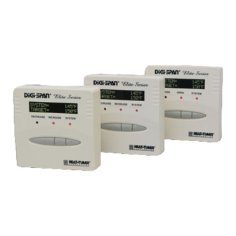
Modulating Controls
MCA: Modulates voltage or 4-20mA devices
MCP: Modulates 135Ω devices
MCF: Modulates floating (3-point) devices
Measures temperature, pressure, vacuum, and humidity
SYSTEM =
TARGET =
DECREASE
Decrease
This Heat-Timer control is strictly an operating control; it should
never be used as a primary limit or safety control. All equipment
must have its own certified limit and safety controls required by local
codes. The installer must verify proper operation and correct any
safety problems prior to the installation of this Heat-Timer control.
SYSTEM =
TARGET =
DECREASE
®
Decrease
o
147
F
o
150
F
INCREASE
SYSTEM
System
WArnIng
SYSTEM =
TARGET =
DECREASE
®
Decrease
o
147
F
o
150
F
INCREASE
SYSTEM
System
MC
®
o
147
F
o
150
F
INCREASE
SYSTEM
System
Advertisement
Table of Contents

Related Manuals for heat-timer DIGI-SPAN Elite MC Series


Summary of Contents for heat-timer DIGI-SPAN Elite MC Series
- Page 1 Decrease System WArnIng This Heat-Timer control is strictly an operating control; it should never be used as a primary limit or safety control. All equipment must have its own certified limit and safety controls required by local codes. The installer must verify proper operation and correct any...
-
Page 2: Table Of Contents
COntEnt MC LAyOut . . . . . . . . . . . . . . . . . . . . . . . . .3 Modulation Target . -
Page 3: Mc Layout
MC LAyOut Output Lights indicate output status Black (120VAC power) 2 Line Alphanumeric Display Displays sensor values and menu settings ® SYSTEM = TARGET = DECREASE INCREASE SYSTEM Decrease System Yellow (System/Boiler Output) Input Terminals EXT+EXT- P+ P- COM24VAC Modulating Output Blue White Display Section Locking Screws... -
Page 4: Mc Overview
MC OvErvIEW 1:4 1:3 1:1.5 12 11 The MC Elite Series controls modulates valves, motors, variable speed drives, or boilers to accurately maintain a set 1:1.25 point based on a PID logic; temperature, pressure, vacuum, or humidity. There are three different models, each provides a different modulating signal. -
Page 5: Mcf Valve Operation
The MC Elite can be wired to either 120VAC using the two Black wires or 24VAC using the right most two terminals on the terminal block on bottom of the control. Heat-Timer recommends the installation of a Surge Suppressor and a Power Switch before the Power Line connection for safety and ease of service. -
Page 6: Wiring Input Terminals
WIrIng Input tErMInALs Input Terminals The MC Elite control will measure the sensor input based upon the options selected from the Sensor Type in Startup menu. All other sensor terminal inputs will be ignored. See "Sensor Type Table" on page 6. T3- EXT+ EXT- P+ P- COM 24VAC WArnIng Class 1 voltage wires (low voltage) must use a different knockout,... -
Page 7: Outdoor Sensor
Control Mode from the Startup menu. However, in Set Point mode, the Outdoor Sensor is optional. In this mode it will be used for the outdoor Cutoff. • Only use the Heat-Timer outdoor sensor (HT# 904220-00). Mounting • Place the sensor in the shade on the north side of the building at least 10'... -
Page 8: Input Wiring Modes
Input Wiring Modes Temperature Temperature Pressure Set Point Outdoor Reset Set Point ® ® ® SYSTEM = SYSTEM = SYSTEM = TARGET = TARGET = TARGET = DECREASE INCREASE SYSTEM DECREASE INCREASE SYSTEM DECREASE INCREASE SYSTEM Decrease System Decrease System Decrease System System Temp... -
Page 9: Wiring A 4 - 20 Ma Actuator Output
Wiring a 4 - 20 mA Actuator Output Common (Red) Current (MCA Only) 4-20mA (White) Signal • An external voltage source is required for the 4-20mA signal. A separate filtered DC power supply providing between 30 to 36 VDC is needed. •... -
Page 10: Button And Navigating Menus
• An option must be accepted in each screen to move to the next screen until all Startup settings are completed. • The System Startup menu sets the main operating modes that apply to the application. These settings must be set by the installer. startup Menus HEAT-TIMER CORP. DIGI-SPAN ELITE Loading Default STANDARD V1.00 c 2008... -
Page 11: Sensor Type
• If English is selected, sensor types in ˚F (Fahrenheit), PSI (Pounds/Square inch), and -SENSOR TYPE-- Hg (Inches of Mercury for Vacuum) will be available. Temp. 230F • If Metric is selected, sensor types in ˚C (Celsius), MPa (Million Pascal), and mm Pres. -
Page 12: Relay Output
relay Output RELAY OUTPUT: (Available Only when Modulation Target=H/C Unit) H/C unit Options: h/C unit, pump Default: h/C unit Pump /<System Startup>/Standard/Sensor Type/Control Mode/.../Relay Output • If the Modulation Target was set to H/C Unit, the Relay Output selection will determine the type of equipment being controlled by the System output (Yellow wires). -
Page 13: Operating Settings
OpErAtIng sEttIngs (Click Button) • The operating menus are for adjusting and fine-tuning the system for enhanced operation and more fuel savings. Different Startup Menu options will offer different Operating menus. Operating Menus Default screen SYSTEM= 68 F Cutoff: Set Point: TARGET= 150 F 70 F... -
Page 14: Reset Ratio
reset ratio Reset Ratio O/S: (Available when Control Mode = Outdoor Reset) Custom Options: From 1(8.00º/1.00º) to 12(1.00º/4.00º), Custom Default: 7(1.00º/1.00º) 1(8.00 / 1.00) 2(4.00 / 1.00) /<Out. Reset>/Reset Ratio 3(3.00 / 1.00) • The Reset Ratio changes the Target temperature based on the outdoor temperature. 4(2.00 / 1.00) The colder it gets outside, the hotter the Target will be. -
Page 15: Outdoor Cutoff
Outdoor Cutoff Cutoff: Options: Off, 30ºF/0ºC to 75ºF/25ºC, On Default: 70ºF/21ºC /Set Point/Cutoff in set point /<Out. Reset>/Cutoff in reset • The outdoor and Cutoff temperatures can be viewed from the default screen by clicking the ▲ or ▼ buttons. •... -
Page 16: Boost
Boost Boost: Options: yes, no Default: no /Settings>/Setback/Boost. • The morning Boost is designed to return the building to comfortable ambient temperatures after the Setback period. The MC Elite will accomplish this by running elevated set point in heating (will add Setback setting to the calculated Target) or reduced set point in cooling (will subtract Setback setting from the calculated Target) for 30 minutes after the opening of the setback terminals T3±... -
Page 17: Run-On
Options: varies based on sensor type . see "sensor trim table" on page 17 . /<Maintenance>/Sys. Trm or Out. Trim System Trim: • The Heat-Timer system sensors are very accurate, and normally require no calibration. +0 F However, sometimes it may be desirable to make small adjustments to the displayed value. -
Page 18: Output Mode
Output Mode Output Mode: (Available on MCA/MCP Only) Auto Options: Auto, Manual Default: Auto Manual /<Maintenance>/Output • The Manual Output Mode provides a way to bypass the control logic to adjust the Output Amount: modulating output manually. • The Output mode is primarily used for equipment testing and troubleshooting. •... -
Page 19: Troubleshooting
trOuBLEshOOtIng pressure sensor Chart sensors and LEDs 0 - 30 0 - 100 0 - 200 0 - 300 Input psI/hg psI/rh% (in mA) range range range range no Display or LED Lights Check the power to the MC Elite. The MC Elite requires 4.08 120VAC power to the Black wires or 24VAC to the right-most terminals. -
Page 20: Actuator Response
Actuator response MCA Elite Does not Move the 4-20mA Actuator Check the Set Point (page 13) and Differential (page 16) settings. If the System Sensor reading is within the Differential band, the MCA Elite may not adjust the modulation position. Otherwise, check the external DC power supply for a voltage between 30 to 36VDC. -
Page 21: Mc Elite Output Modes Wiring
• Heat-Timer DOES NOT recommend sharing the power source to the control with any pumps or heavy electric equipment. • Heat-Timer Corp. is aware that each installation is unique. Thus, Heat-Timer Corp. is not responsible for any installation related to any electrical or plumbing diagram generated by Heat-Timer Corp. -
Page 22: Specifications
spECIFICAtIOns voltage Input: ..120 VAC 60 Hz(2 Black wires) /24VAC 60 Hz (24VAC terminals) (Only One Power Source) power Consumption: ..........5 VA Max Operating temperature: . -
Page 23: Warranty
WARRANTIES AND LIMITATIONS OF LIABILITY AND DAMAGE: Heat-Timer Corporation warrants that it will replace, or at its option, repair any Heat-Timer Corporation manufactured product or part thereof which is found to be defective in material workmanship within one year from the date of installation only if the warranty registration has been properly filled out and returned within 30 days of the date of installation. - Page 24 20 New Dutch Lane, Fairfield, NJ 07004 973-575-4004 • Fax 973-575-4052 • http://www.heat-timer.com MC-Elite Installation and Operation Manual...
Need help?
Do you have a question about the DIGI-SPAN Elite MC Series and is the answer not in the manual?
Questions and answers