Table of Contents
Advertisement
Quick Links
Installation and Operation Manual
Domestic Hot Water Boiler or Direct or
Indirect Water Heater and Recirculating
Pump Control with Setback Schedule
This Heat-Timer control is strictly an operating control; it should
never be used as a primary limit or safety control. All equipment
must have its own certified limit and safety controls required by local
codes. The installer must verify proper operation and correct any
safety problems prior to the installation of this Heat-Timer control.
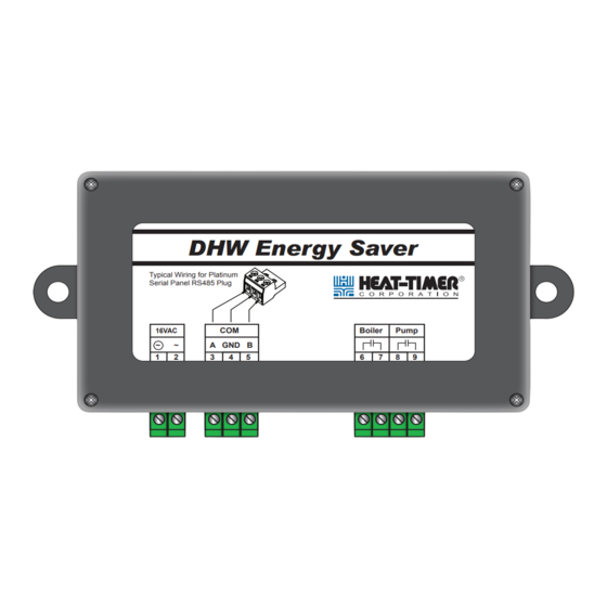
DHW Energy Saver
Typical Wiring for Platinum
Serial Panel RS485 Plug
COM
16VAC
~
~
A GND B
1
2
3
4
5
WARNING
DHW
Energy Saver
Boiler
Pump
6
7
8
9
Advertisement
Table of Contents

Related Manuals for heat-timer DHW Energy Saver


Summary of Contents for heat-timer DHW Energy Saver
- Page 1 16VAC A GND B WARNING This Heat-Timer control is strictly an operating control; it should never be used as a primary limit or safety control. All equipment must have its own certified limit and safety controls required by local codes. The installer must verify proper operation and correct any...
-
Page 2: Table Of Contents
Demand Schedule Copy Schedule INTERNET ALARMS THROUGH ICMS Sensor Fault Communication Error TROUBLESHOOTING AND LEDS PIPING/WIRING TO WATER HEATER PIPING/WIRING TO BOILER AND INDIRECT WATER HEATER PIPING/WIRING TO BOILER AND A TEMPERING VALVE SPECIFICATION DHW Energy Saver Installation and Configuration Manual... -
Page 3: Overview
DHW Energy Saver Typical Wiring for Platinum Serial Panel RS485 Plug Boiler Pump 16VAC A GND B 16 VAC Communication to DHW boiler and (transformer Heat-Timer DHW circulating Provided) Platinum Control pump output relays DHW Energy Saver Installation and Configuration Manual... -
Page 4: Installation
• T he DHW Energy Saver RS485 terminals are wired to the Platinum main board’s RS485 (under the PCB board). • F ollow the wiring as per the graph on the right. ALERT DO NOT connect the DHW Energy Saver to the RS485 on the PCB board Platinum RI board. Instead, connect the DHW Energy Saver RS485 to the Platinum main board. • M aximum wiring length should not exceed 100 Feet. Use 18 gauge 2-conductor shielded wire (#18). Connect the shield to the... -
Page 5: Boiler Or Direct/Indirect Water Heater Wiring
• T he sensors must be inserted in ⅜”ID NPT well (HT# 904011-00 or TEMP 2 equivalent). Supply Temperature Sensor • T he Supply Temperature Sensor is required to be connected to the Platinum Aux Temp 0 input terminals for the DHW Energy Saver to control the boiler/water heater relay. • T he Supply sensor must be installed in any of the boiler or water heater aquastat fittings or no more than 10 Ft past the outlet of the boiler/water heater, before any takeoffs. Return Temperature Sensor • T he return Temperature Sensor is included but optional. It should be connected to the Platinum Aux Temp 1 input terminals for the DHW Energy Saver to control the Pump relay. • T he Return sensor should be installed less than 3 feet from the return circulator on the return line. DHW Energy Saver Installation and Configuration Manual... -
Page 6: Platinum Control Menu Settings
- DHW DEMAND SCHED - <Supply Settings> Setpoint 120 F <Return Settings> MON#1 Peak Diff 20 F Demand Schedule Peak Time 6:00Am Light Diff 40 F Copy Schedule Light Time 10:00Pm ICMS Web Menu Settings DHW Energy Saver Installation and Configuration Manual... -
Page 7: Using The Supply Or Return Sensor
40 F • A ny of the differentials is subtracted from the set point to determine the temperature at which the boiler/water heater or pump relay will energize. • T he DHW Energy Saver has two independent differentials for each of the supply and return. The Peak Differential is used to keep a tight control over the DHW temperature during DHW RETURN PEAK DIFF heavy usage. This differential is used when the DHW Schedule is in the Peak period. Its 20 F value must be less than or equal to the Light Differential for the same sensor. • T he Light Differential is used during the night, low DHW usage, or when a tight control of the temperature is not required. It allows the boiler or pump relay to turn on for a slightly DHW RETURN LIGHT DIFF longer period. However, due to the reduced usage, the relay will remain off for a much 40 F longer period. This type of differential is used when the DHW Schedule is in the Light period. Its value must be greater than or equal to the Peak Differential for the same sensor. DHW Energy Saver Installation and Configuration Manual... -
Page 8: Demand Schedule
The boiler/water heater must have its operating and limit controls installed and wired in a way so that the Supply sensor fault or DHW Energy Saver communication Error will not cause a hazardous situation. It is the responsibility of the installer to make sure of the system operation and users safety during sensor fault or communication error. -
Page 9: Piping/Wiring To Water Heater
Light Differential 15°F Light Differential 10°F Heat-Timer is aware that each installation is unique Thus, is not responsible for any installation related to any electrical or plumbing diagram generated by Heat-Timer The provided illustrations are to demonstrate Heat-Timer’s control operating concept only... -
Page 10: Piping/Wiring To Boiler And Indirect Water Heater
Light Differential 60°F (Condensate Boiler) Heat-Timer is aware that each installation is unique Thus, is not responsible for any installation related to any electrical or plumbing diagram generated by Heat-Timer The provided illustrations are to demonstrate Heat-Timer’s control operating concept only... -
Page 11: Piping/Wiring To Boiler And A Tempering Valve
Sensor Shield (Connect to O) Heat-Timer is aware that each installation is unique Thus, is not responsible for any installation related to any electrical or plumbing diagram generated by Heat-Timer The provided illustrations are to demonstrate Heat-Timer’s control operating concept only... -
Page 12: Specification
Weight . . . . . . . . . . . . . . . . . . . . . . . . . . . . . . . . . . . . . . . . . . . . . . . . . . . . . . 1 Pound 20 New Dutch Lane, Fairfield, NJ 07004 Ph: (973) 575-4004 • Fax: (973) 575-4052 http://www.heat-timer.com...
Need help?
Do you have a question about the DHW Energy Saver and is the answer not in the manual?
Questions and answers