
Subscribe to Our Youtube Channel
Related Manuals for Standby LB200


Summary of Contents for Standby LB200
- Page 1 Operating Manual Valid for: 506584xxxxx – LB200 469 – 1847 mm Document: 50658400001980 (0) Language: English Issue date: 11/2023 standbygroup.se Page 1 (SE)+46 520 494440 • email: info-se@standbygroup.com...
-
Page 2: Liability Notice
The body builder must define the means and materials required to assemble the equipment in order to deliver the vehicle equipped according to the regulations. Standby is not responsible for errors resulting from a wrong definition of the type of mounting system, the reinforcements, the holes in the roof panel, the condition and quality of the mounting system, the use of anchoring points by the vehicle manufacturer and the definition of the power supply and protection of the system according to the energy source of the vehicle. -
Page 3: Safety Instructions
Safety Instructions WARNING ABOUT OPTICAL RADIATION All optical components are classified as low risk in accordance with DIN EN 62471. Only look into the light beam of the components for a short time (max. 4 minutes) with the paint cap on! Minimum distance from light source to eye 0.2 m. - Page 4 Mounting the light bar The brackets described here are NOT included in the scope of delivery but are recommended! Part number: 50658400030 Components of the mounting bracket: Retaining clips for connectors Bracket Compensation angle Cover (can be mounted optionally) Assembly: Insert the M8 hexagon screws into the grooves provided in the base plate and tighten the nuts so that the bracket can still...
- Page 5 Mounting the light bar Align the LB200 on the vehicle roof by moving the brackets and tighten the M8 nuts with 6 Nm. Insert the plug connector into the retaining clips provided and guide the cable with the cable ties provided.
- Page 6 Mounting the light bar In the case of heavily curved vehicles in the side area, the compensation angles can be bent accordingly and adjusted slightly if necessary. Connection points to the vehicle roof. Connection points to the roof rails. At least four connection points should be used per bracket.
- Page 7 Mounting the light bar Tighten the screw (torque 2-3Nm, use liquid screw locking agent). standbygroup.se (SE)+46 520 494440 • email: info-se@standbygroup.com Page 7...
-
Page 8: Electrical Connection
Electrical connection standbygroup.se Page 8 (SE)+46 520 494440 • email: info-se@standbygroup.com... - Page 9 Flash pattern setting To change the flash pattern of the LB200, the light bar is first connected to the power supply. Now the flash pattern can be set by pressing the yellow line (synch) against +UB for < 1s. The flash pattern changes according to the table below.
-
Page 10: Technical Data
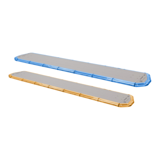
Technical Data TECHNICAL DATA Operating Voltage 12/24 VDC (10 … 30 VDC) Current Consumption 3 – 10 A, depending to lightbar length LED-Colour blue, amber Dome Colour clear Flash pattern Single-, Double-, Tripple-, Quadruple flash, alternating or synchronous, ICAO, Rotating Mounting fix mount Protection Class... - Page 11 Notes standbygroup.se (SE)+46 520 494440 • email: info-se@standbygroup.com Page 11...
- Page 12 standbygroup.se Page 12 (SE)+46 520 494440 • email: info-se@standbygroup.com...
Need help?
Do you have a question about the LB200 and is the answer not in the manual?
Questions and answers