Advertisement
Quick Links
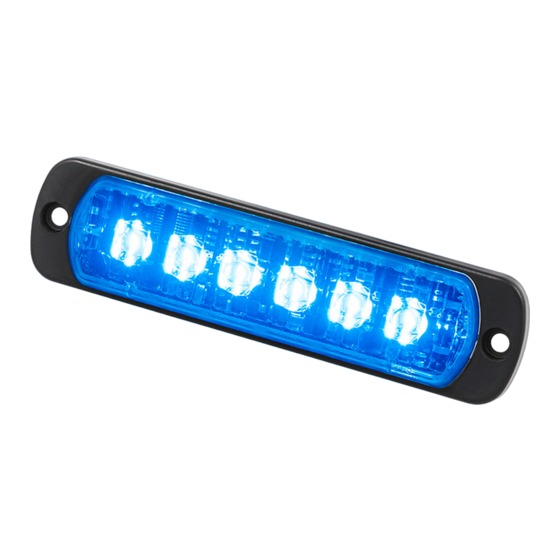
L52 2C
Thank you for choosing a product from Standby.
Technical Data
Lens
Diodes
Cable
Power
Ambient temperature
Power consumption
Size
Approvals
Included
Synchronizing
Preset Settings
Part
Color 1
number
45257031
Blue
45257032
Blue
45257033
Blue
45257034
Blue
45267031
Red
45287031
Amber
45287032
Green
45287034
Amber
To change the flash pattern setting, see Flash Pattern. To change the sync mode setting, see Sync Mode. To change the input
X2/X3 setting, see Input X2/X3.
WAM4522CB
Flash pattern
Color 2
Color 1
Color 2
Amber
Red
White
Green
Double
White
White
Amber
Red
Polycarbonate
6+6 high power LED
2 m, basic version
10-30 V DC
-40ºC to +85ºC
0.8 A peak at 13.8 V
0.4 A peak at 27.6 V
113 x 28 x 9 mm
Light: ECE R65 (E5)
EMC: ECE R10 (E5)
IP6K9K
1 x L52 Lamp 2C
1 x gasket
1 x assembly kit
12 V: Up to 12 lamps
24 V: Up to 8 lamps
Sync mode
Color 1
Double
Steady
Steady
Double
Simultaneous
Double
Steady
Double
Steady
1
L52 2C – Manual
Input X2/X3
Color 2
Color 1
Color 2
Alternate
Pull down
Pull down
Standby AB – standbygroup.se
Advertisement

Subscribe to Our Youtube Channel
Related Manuals for Standby L52 2C


Summary of Contents for Standby L52 2C
- Page 1 L52 2C – Manual L52 2C Thank you for choosing a product from Standby. Technical Data Lens Polycarbonate Diodes 6+6 high power LED Cable 2 m, basic version Power 10-30 V DC Ambient temperature -40ºC to +85ºC Power consumption 0.8 A peak at 13.8 V 0.4 A peak at 27.6 V...
- Page 2 L52 2C – Manual Flash Pattern Introduction The flash pattern setting controls the flash pattern. There are seven available combinations of flash patterns, see table. • Double, Triple and Steady burn are built-in flash patterns and no control system is needed.
- Page 3 L52 2C – Manual Setting the Flash Pattern WARNING Risk of eye damage. Do not look into the beam at close range. 1. If already in configuration mode, go to step 6. 2. If the lamp is connected to the power supply, disconnect it.
- Page 4 L52 2C – Manual 6. Temporarily connect the white wire to ground to enter configuration mode for flash pattern. 7. Count the number of blank flashes (lamp off) per flash sequence to find out the current flash pattern setting. 8. Temporarily connect the white wire to ground to change to the next version of flash pattern. Each time the white wire is temporarily connected to ground the next version of flash pattern is selected.
- Page 5 L52 2C – Manual Sync Mode Introduction The sync mode setting controls how the flashing of two or more lamps is synchronized. There are four available combinations of sync mode, see table. • Simultaneous means that the lamps are in sync, that is they come on and go off at the same time.
- Page 6 L52 2C – Manual Setting the Sync Mode WARNING Risk of eye damage. Do not look into the beam at close range. 1. If already in configuration mode, go to step 6. 2. If the lamp is connected to the power supply, disconnect it.
- Page 7 L52 2C – Manual 6. Temporarily connect the blue wire to ground to enter configuration mode for sync mode. 7. Count the number of bright flashes of color 1 per flash sequence to find out the current sync mode setting.
- Page 8 L52 2C – Manual Input X2/X3 Introduction The input X2/X3 controls how the colors of the lamp are activated. There are four available combinations of input X2/X3, see table. • Pull down means that the color is activated by a sourcing signal (+).
- Page 9 L52 2C – Manual 5. Within 1 to 6 sec: temporarily connect the white wire to ground and let it stay connected for at least 2 sec. The lamp enters configuration mode and a flash sequence indicating the current settings starts.
- Page 10 L52 2C – Manual Factory Reset Introduction The settings can be changed back to the factory settings. The factory settings are the following(color 1/color 2): • Flash pattern - Double/Double • Sync mode - Simultaneous/Alternate • Input X2/X3 - Pull down/pull down...
- Page 11 L52 2C – Manual 5. Within 1 to 6 sec: temporarily connect the white wire to ground and let it stay connected for at least 2 sec. The lamp enters configuration mode and a flash sequence indicating the current settings starts.
- Page 12 L52 2C – Manual Connections The function of each wire and how to connect the wires depend on which version of flash pattern and input X2/X3 that is selected, see tables below. For more information about flash pattern and input X2/X3, see Flash Pattern and Input X2/X3.
- Page 13 L52 2C – Manual Table 2. Connections when flash pattern Steady burn 1/Steady burn 1 is selected. Wire Functions Connect to Black Power supply Good and suitable ground Power supply 10-30 V DC via a 5 A fuse Blue Activating Steady burn for...
- Page 14 L52 2C – Manual Table 3. Connections when flash pattern Steady burn 2/Steady burn 2 is selected. Wire Functions Connect to Black Power supply Good and suitable ground Power supply 10-30 V DC via a 5 A fuse Blue Activating Steady burn for...
- Page 15 L52 2C – Manual Table 4. Connections when flash pattern Double/Steady burn 3 is selected. Wire Functions Connect to Black Power supply Good and suitable ground Power supply 10-30 V DC via a 5 A fuse Activating the flashing of...
- Page 16 L52 2C – Manual Installation CAUTION The lamp must be mounted on a flat surface. To prevent moisture from entering the lamp through the cable end, make sure that the cable end is sealed or located in a dry part of the vehicle.
Need help?
Do you have a question about the L52 2C and is the answer not in the manual?
Questions and answers