Advertisement
Quick Links
W3
Safety
WARNING
!
This product contains high intensity LED devices. To prevent eye damage, do not look into the
light beam at close range.
Technical Data
Attribute
Lens
Color, lens
Color, LED, End modules
Color, LED, Inboard modules
Cable
Voltage
Power consumption
Length
Height
Width
Interface
Operating temperature
Approvals
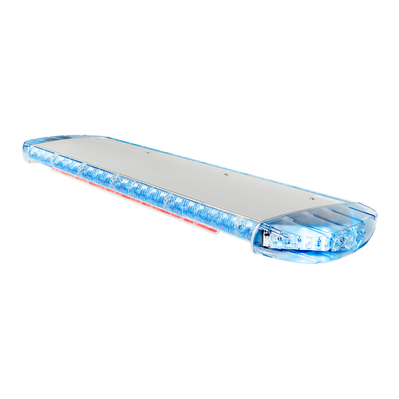
Parts Overview
WAM8W3A
Units
Polycarbonate
Clear or blue
Blue, amber, red or blue/amber
Blue/amber, blue/red. Blue/white, white/amber, blue/green,
red/empty, white/empty, empty/amber, blue/empty or
red/amber
4.5 m
12- 24 V DC
20 A with peak at 30 A for less than 50 ms
930, 1100, 1270, 1440, 1600, 1770 or 1940 mm
Corner module: 65 mm
Inboard module: 47 mm
280 mm
CAN bus of a Standby Control System or break out box
-40°C – +85°C
ECE R6, ECE R7, ECE R10, ECE R65, ICAO
A.
Front
B.
Rear
1.
Front module
2.
Rear module
3.
Corner module
4.
Alley right
5.
Aerodynamic cover
6.
T-rail
4.5 m cable / Cannon connector (optional)
Controllpanel with fixingsystem
1
Standby AB – standbygroup.se
W3 – Manual
Advertisement

Related Manuals for Standby W3


Summary of Contents for Standby W3
- Page 1 Corner module: 65 mm Inboard module: 47 mm Width 280 mm Interface CAN bus of a Standby Control System or break out box Operating temperature -40°C – +85°C Approvals ECE R6, ECE R7, ECE R10, ECE R65, ICAO Parts Overview...
- Page 2 W3 – Manual Dimensions WAM8W3A Standby AB – standbygroup.se...
- Page 3 W3 – Manual Break out box connection to W3 Lightbar Color examples: • Blue/Amber Lightbar, Blue=1 Amber=2 • Red/Amber Lightbar, Red= 1 Amber =2 Note Input X18 is only used during configuration and should always be set back to 0 when configuration is done.
- Page 4 Power supply Good and suitable ground Power supply 12-24 V DC via a 20 A fuse Yellow CAN bus of a Standby Control System or break out box CAN bus of a Standby Green Control System or break out box WAM8W3A Standby AB –...
-
Page 5: Installation
2. Pre install lightbar with the brackets on the vehicle roof rails. 3. Aline the lightbar with the B-pillar. The Standby label is placed on the lightbar FRONT part. 4. Cabling preparations: 5. Pre install the lightbar and brackets on the vehicle roof 1. - Page 6 2. Pre install lightbar with the brackets on the vehicle roof rails. 3. Aline the lightbar with the B-pillar. The Standby label is placed on the lightbar FRONT part. 4. Cabling preparations: 5. Pre install the lightbar and brackets on the vehicle roof 1.
- Page 7 W3 – Manual Maintenance Note Use a mild car wash shampoo and a sponge that is gentle/appropriate to the lightbar surface as well as the vehicle surface. CAUTION When using high-pressure cleaner: Water pressure at a maximum of 80 bar.
Need help?
Do you have a question about the W3 and is the answer not in the manual?
Questions and answers