
Related Manuals for Flowserve Limitorque L120-190


Summary of Contents for Flowserve Limitorque L120-190
- Page 1 USER INSTRUCTIONS Limitorque L120-190 through L120-2000 Installation ® Operation FCD LMENIM1203-01-A4 – 05/15 Maintenance Experience In Motion...
- Page 2 Limitorque L120-190 through L120-2000 FCD LMENIM1203-01-A4 – 05/15 ®...
-
Page 3: Table Of Contents
7.1.3 Reassembling Actuator Sizes L120-190, -420 and -800 7.1.4 Gaskets 7.2 L120-2000 7.2.1 Drive 2 Disassembly (Thrust Housing Only) 7.2.2 Drive 1 Disassembly (Torque Housing) 7.2.3 Drive 1 (Torque Housing) Reassembly 7.2.4 Drive 2 (Thrust Housing Only) Reassembly Standard Wiring Diagrams Troubleshooting flowserve.com... - Page 4 Limitorque L120-190 through L120-2000 FCD LMENIM1203-01-A4 – 05/15 ® 10 How to Order Parts 11 EC Declaration of Conformity Figures Figure 2.1 – L120-190 through 2000 Figure 4.1 – Double Torque Switch Figure 4.2 – Setting Torque Switch Figure 4.3 – Ring Tongue Terminal Figure 4.4 –...
-
Page 5: Introduction
CAUTION: Directs the user’s attention to general precautions that, if not followed, could result in personal injury and/or equipment damage. NOTE: Highlights information critical to the user’s understanding of the actuator’s installation and operation. flowserve.com... -
Page 6: Initial Inspection And Storage Instructions
Limitorque L120-190 through L120-2000 FCD LMENIM1203-01-A4 – 05/15 ® Initial Inspection and Storage Instructions L120 Series actuators operate without modification in any rising or non-rising stem application for linear-action valves. The actuators meet rigid safety requirements and are available in weatherproof, explosionproof, and submersible configurations. -
Page 7: Product Identification
• Locked rotor amps • RPM • Duty • Full load amps • Horsepower • Insulation class • Phase • Space heater size • Motor code • Service Factor • Connection diagram • Cycles • Ambient temperature • Start torque flowserve.com... -
Page 8: Inspection And Recording
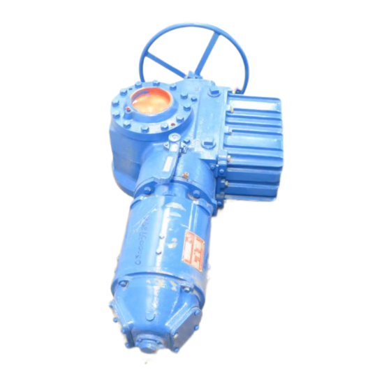
Limitorque L120-190 through L120-2000 FCD LMENIM1203-01-A4 – 05/15 ® Figure 2.1 – L120-190 through 2000 Declutch Lever Motor Actuator Nameplate (hidden) Housing Handwheel Limit Switch and Controls Compartment 2.2 Inspection and Recording Upon receipt of the actuator, inspect the condition of the equipment and record nameplate information. 1. - Page 9 4. Replace all plastic caps or plugs with pipe plugs and ensure that all covers are tight. 5. If the actuator is mounted on a valve and the stem protrudes from the actuator, a suitable stem cover must be provided. flowserve.com...
-
Page 10: Actuator Weights
Limitorque L120-190 through L120-2000 FCD LMENIM1203-01-A4 – 05/15 ® Actuator Weights The approximate L120 actuator weights are provided below: Table 3.1 – Actuator Weights Drive 1 Weight Side HW Drive 2 Weight Side HW Actuator Size Control Types L120-190 UEC/Clamshell 1065 1065 L120-420... -
Page 11: Installation Instructions
WARNING: Do not exceed any design limitations or make modifications to this equipment without first consulting Limitorque. flowserve.com... -
Page 12: Safety Practices
CAUTION: Do not depress the declutch lever during motor operation to stop valve travel. a CAUTION: Do not use replacement parts that are not genuine Flowserve Limitorque parts, as serious personal injury and/or damage to the actuator and valve may result. -
Page 13: Mounting Base
NOTE: For complete mounting dimensions, see sales brochure LMENBR1200. 4.4 Double Torque Switch The torque switch is designed to protect the actuator in open and close directions. Figure 4.1 – Double Torque Switch NOTE: See Caution and Note on following page. flowserve.com... -
Page 14: Setting Torque Switch
Limitorque L120-190 through L120-2000 FCD LMENIM1203-01-A4 – 05/15 ® a CAUTION: Disconnect all incoming power before opening limit switch compartment or working on the torque switch. • Do not use abrasive cloth to clean the contacts on the torque switch. •... -
Page 15: Balancing Torque Switch
4.4.3 Torque Switch Terminal Connections Wiring connections to the L120 geared limit switch, torque switch, and marathon terminal strips are to be made using ring-tongue terminals as shown below: Figure 4.3 – Ring Tongue Terminal See Table 4.3, next page flowserve.com... -
Page 16: Geared Limit Switch - Rotor Type
Limitorque L120-190 through L120-2000 FCD LMENIM1203-01-A4 – 05/15 ® Table 4.3 – Terminal Dimensions By Cable Size Thomas & Screw Hole Insulation Betts P/N 22-16 Vinyl 18RA-10 18-14 Vinyl 14RB-10 12-10 Vinyl 14RC-10 1.06 Terminals are to be crimped using Thomas & Betts crimping tool WT111M. 4.5 Geared Limit Switch –... -
Page 17: Figure 4.4 - Geared Limit Switch
3720 1240 58:1 86:1 L120-2000 43:1 1210 12100 4234 1413 71:1 7400 2566 Figure 4.4 – Geared Limit Switch Set the limit switch as shown on the following page. All item letters and piece numbers refer to Figure 4.5. flowserve.com... -
Page 18: Figure 4.5 - Setting Geared Limit Switch
Limitorque L120-190 through L120-2000 FCD LMENIM1203-01-A4 – 05/15 ® Figure 4.5 – Setting Geared Limit Switch Contact Plunger Rotor Cam Contact Open Contact Close Clutch Screw Intermediate Shaft Piece Quantity Description Gear Frame Assembly 8-Switch Contact Block Assembly Rotor Segment (short) Rotor Shaft Clutch Machine Screw... -
Page 19: Combination Of Contacts
4.6.1 Local Position Indication The local dial position indicator is factory-built per the application. The position indicator can only be adjusted when mounted on the valve. Figure 4.6 – Position Indicators MID-TRAVEL NOTE: See the setting procedure on the following page. flowserve.com... -
Page 20: Remote Position Indication
Limitorque L120-190 through L120-2000 FCD LMENIM1203-01-A4 – 05/15 ® To set the local position indicator: 1. Disconnect all incoming power and remove Limit Switch Compartment Cover (piece #200-1 of Figure 7.3 for L120-190, -420 and -800, and Figure 7.7 for L120-2000). 2. -
Page 21: Operation
3. If the valve stem is not visible, remove the stem cover or handwheel cover plate to observe the output direction of the drive sleeve. 4. Engage manual operation and hand crank the valve well away from end-of-travel positions. 5. Turn on power supply and push the “open” button on the pushbutton station. flowserve.com... -
Page 22: Typical Wiring Diagram
Limitorque L120-190 through L120-2000 FCD LMENIM1203-01-A4 – 05/15 ® 6. Check output rotation: • If phase rotation is correct, the valve should begin to open. • If valve begins to CLOSE, STOP IMMEDIATELY. Incorrect phase rotation will lead to serious damage if the valve seats. -
Page 23: Motor Operation
Axial worm movement causes movement of the bearing cartridge that is geared to the Torque Switch (piece #300). The torque switch is graduated and adjustable so it may be set to interrupt power to the motor at a predetermined output torque level. flowserve.com... -
Page 24: Maintenance
Limitorque L120-190 through L120-2000 FCD LMENIM1203-01-A4 – 05/15 ® Maintenance 6.1 Lubrication The L120 series actuators have a totally sealed gear case, factory-lubricated with grease. The gear case can be mounted in any position. a CAUTION: When the actuator is mounted in an upside-down orientation, the worm may not be completely immersed in lubricant. -
Page 25: Factory Lubricant
• Not contain any grit, abrasive, or fillers. • Comply with a slump-prefer NLGI-00 grade. • Not be corrosive to steel gears, ball, or roller bearings. • Have a dropping point above 316°F (158°C) for temperature ranges of 0°F to 225°F (-18°C to 107°C). flowserve.com... -
Page 26: Disassembly And Reassembly
Limitorque L120-190 through L120-2000 FCD LMENIM1203-01-A4 – 05/15 ® Disassembly and Reassembly c WARNING: See sections 4.1 and 4.2 Safety Precautions and Safety Practices prior to disassembly. c WARNING: Potential High Pressure Vessel. Before removing or disassembling your actuator, ensure that the valve or other actuated device is isolated and is not under pressure. a CAUTION: Turn off all power services before attempting to perform service on the actuator. -
Page 27: L120-190, 420, 800 Disassembly
Housing (piece #1). See Step No. 21 to further disassemble the cartridge. 11. Remove Housing Cover (piece #3). flowserve.com... -
Page 28: Reassembling Actuator Sizes L120-190, -420 And -800
Limitorque L120-190 through L120-2000 FCD LMENIM1203-01-A4 – 05/15 ® c WARNING: Do not remove if a thrust load is on the actuator or if the valve is under pressure and not fully open, as personal injury may result. 12. Lift complete drive sleeve assembly from actuator housing. The drive sleeve assembly consists of Lock Nut (piece #39), Stem Nut (piece #12), Drive Sleeve (piece #8), Upper Thrust Bearings (piece #40, #67), Worm Gear (piece #13), Worm Gear Spacer (piece #36) and Lower Thrust Bearing (piece #14). -
Page 29: Gaskets
2. Install actuator drive sleeve assembly complete with bearings. 3. Install housing cover and measure the gap between the housing cover and the main housing. 4. Add 10% to the measurement. Use the closest nominal gasket thickness or combination available. flowserve.com... -
Page 30: Figure 7.1 - L120-190 And -420 Drive Sleeve Side View (Refer To Table 8.1 For Parts List)
Limitorque L120-190 through L120-2000 FCD LMENIM1203-01-A4 – 05/15 ® Figure 7.1 – L120-190 and -420 Drive Sleeve Side View (Refer to Table 7.1 for parts list) Drawing 01-608-0115-4... -
Page 31: Figure 7.2 - L120-190 And -420 Worm Shaft Side View (Refer To Table 8.1 For Parts List)
Limitorque L120-190 through L120-2000 FCD LMENIM1203-01-A4 – 05/15 ® Figure 7.2 – L120-190-and 420 Worm Shaft Side View (Refer to Table 7.1 for parts list) Drawing 01-608-0116-4 flowserve.com... -
Page 32: Figure 7.3 - L120-190 And -420 Top View (Refer To Table 8.1 For Parts List)
Limitorque L120-190 through L120-2000 FCD LMENIM1203-01-A4 – 05/15 ® Figure 7.3 – L120-190 and -420 Top View (Refer to Table 7.1 for parts list) Drawing 01-608-0117-4... -
Page 33: Figure 7.4 - L120-800 Drive Sleeve Side View (Refer To Table 8.1 For Parts List)
Limitorque L120-190 through L120-2000 FCD LMENIM1203-01-A4 – 05/15 ® Figure 7.4 – L120-800 Drive Sleeve Side View (Refer to Table 7.1 for parts list) Drawing 01-608-0138-4 flowserve.com... -
Page 34: Figure 7.5 - L120-800 Worm Shaft Side View (Refer To Table 8.1 For Parts List)
Limitorque L120-190 through L120-2000 FCD LMENIM1203-01-A4 – 05/15 ® Figure 7.5 – L120-800 Worm Shaft Side View (Refer to Table 7.1 for parts list) Drawing 01-608-0136-4... -
Page 35: Figure 7.6 - L120-800 Top View (Refer To Table 8.1 For Parts List)
Limitorque L120-190 through L120-2000 FCD LMENIM1203-01-A4 – 05/15 ® Figure 7.6 – L120-800 Top View (Refer to Table 7.1 for parts list) Drawing 01-608-0137-4 flowserve.com... -
Page 36: Table 7.1 - L120-190, -420 And -800 Typical Parts List
Limitorque L120-190 through L120-2000 FCD LMENIM1203-01-A4 – 05/15 ® Table 7.1 – L120-190, -420 and -800 typical parts list Piece No. Quantity Description Piece No. Quantity Description Housing Seal Retainer Plate Declutch Housing Lock Nut Housing Cover Upper Thrust Bearing Cup Spring Cartridge Cap Lower Thrust Bearing Cone Handwheel... - Page 37 Socket Head Cap Screw 200-3 various Lockwasher (L120-190, 420) 56-18 various Socket Head Cap Screw M.D.P.I. Sight Glass 56-19 Socket Head Set Screw Torque Switch 56-20 Socket Head Set Screw Geared Limit Switch 56-21 Lockwasher Mechanical Dial Position Indicator flowserve.com...
-
Page 38: L120-2000
Limitorque L120-190 through L120-2000 FCD LMENIM1203-01-A4 – 05/15 ® 7.2 L120-2000 c WARNING: See sections 4.1 and 4.2 Safety Precautions and Safety Practices. NOTE: The L120-2000 Drive 2 is a thrust-type actuator consisting of an L120-2000 Drive 1 torque- type actuator mounted on a thrust bearing assembly. For torque-only actuators see Section 8.2.2, Drive 1 Disassembly (Torque Housing). - Page 39 19. Remove Locking Nut (piece #16-10). a CAUTION: Declutch Housing is under spring load. 20. Remove Declutch Housing (piece #2): A. Pull Bearing Cartridge Stem (piece #16-8) out partially. B. Remove Thrust Washers (piece #16-2), Torque Limit Sleeve (piece #16-5) and Springs (piece #16-3). flowserve.com...
-
Page 40: Drive 1 (Torque Housing) Reassembly
Limitorque L120-190 through L120-2000 FCD LMENIM1203-01-A4 – 05/15 ® 21. Remove bearing cartridge/worm assembly from actuator. To disassemble further: A. Loosen two setscrews on Bearing Cartridge Cap (piece #16-1), and unscrew Bearing Cartridge Stem (piece #16-8). B. Slide bearing cartridge cap off toward worm threads. C. - Page 41 24. Ensure that declutch shaft bears against declutch cap, push collar against top of housing, and tighten collar setscrew. 25. Ensure that Oil Seal (piece #54-8) is in place. 26. Install Declutch Lever (piece #11) and tighten setscrew. 27. Rotate declutch lever clockwise, hold in position, and install Declutch Lever Stop (piece #93). flowserve.com...
-
Page 42: Drive 2 (Thrust Housing Only) Reassembly
Limitorque L120-190 through L120-2000 FCD LMENIM1203-01-A4 – 05/15 ® 28. Install Clutch Tripper (piece #34-A, 34-B) and Tripper Spring (piece #58). 29. Install Declutch Housing Cover (piece #3) and Declutch Cover Gasket (piece #54-11). 30. Ensure that Handwheel Oil Seal (piece #54-8) is in place. 31. -
Page 43: Figure 7.7 - L120-2000 Drive Sleeve Side View (Torque Base) (Refer To Table 8.2 For Parts List)
Limitorque L120-190 through L120-2000 FCD LMENIM1203-01-A4 – 05/15 ® Figure 7.7 – L120-2000 Drive Sleeve Side View (Refer to Table 8.2 for parts list) Drawing 01-608-0141-4_2of3 flowserve.com... -
Page 44: Figure 7.8 -L120-2000 Top View (Refer To Table 8.2 For Parts List)
Limitorque L120-190 through L120-2000 FCD LMENIM1203-01-A4 – 05/15 ® Figure 7.8 -L120-2000 Top View (Refer to Table 8.2 for parts list) Drawing 01-413-0036-4... -
Page 45: Figure 7.9 - L120-2000 Side View (Refer To Table 8.2 For Parts List)
Limitorque L120-190 through L120-2000 FCD LMENIM1203-01-A4 – 05/15 ® Figure 7.9 – L120-2000 Side View (Refer to Table 8.2 for parts list) Drawing 01-608-0141-4_3of3 flowserve.com... -
Page 46: Figure 7.10 - L120-2000 Exploded View
Limitorque L120-190 through L120-2000 FCD LMENIM1203-01-A4 – 05/15 ® Figure 7.10 - L120-2000 Exploded View Drawing 08-408-0002-4... -
Page 47: Table 7.2 - L120-2000 Typical Parts List
Soc Head Set Screw 42-1 Declutch Fork 56-13 Tripper Bolt 42-4 Fork Roller 56-15 42-5 Roller Pinion 56-16 44-1 Bearing Locknut 56-17 Soc Head Set Screw Clutch Compression Spring 56-20 Soc Head Set Screw Spring Washer 56-21 Soc Head Set Screw flowserve.com... - Page 48 Limitorque L120-190 through L120-2000 FCD LMENIM1203-01-A4 – 05/15 ® Table 7.2 Continued - L120-2000 typical parts list Piece No. Quantity Description Piece No. Quantity Description Tripper Spring Gear Insert Hinge Split Ring 70-1 Hex Head Cap Screw Retaining Ring 70-2 Lockwasher Motor Adaptor Gasket Bearing Cup...
-
Page 49: Standard Wiring Diagrams
CHECKED TITLE WIRING DIAGRAM MECHANICAL OVERLOAD OCCURS DURING CLOSING CYCLE. APPROVED OPENING TORQUE SWITCH INTERRUPTS CONTROL CIRCUIT IF 1ST ORDER NO. DRAW ING NO. STANDAR D MECHANICAL OVERLOAD OCCURS DURING OPENING CYCLE. DESCRIPTION DATE 16-476-1047-3 REDRAWN DATE REVISION 01-6-88 flowserve.com... -
Page 50: Figure 8.2 - Wiring Diagram - Integral Controls
Limitorque L120-190 through L120-2000 FCD LMENIM1203-01-A4 – 05/15 ® Figure 8.2 – Wiring Diagram – Integral Controls... -
Page 51: Figure 8.3 - Wiring Diagram - Ncu
Limitorque L120-190 through L120-2000 FCD LMENIM1203-01-A4 – 05/15 ® Figure 8.3 – Wiring Diagram – NCU flowserve.com... -
Page 52: Troubleshooting
Limitorque L120-190 through L120-2000 FCD LMENIM1203-01-A4 – 05/15 ® Troubleshooting Problem Check A. Control wiring and motor reversing contactor. B. Geared limit switch setting. C. Setting rod to see that it has been backed off after Geared limit switch fails to stop valve travel. each side of the switch has been set. -
Page 53: How To Order Parts
L120-190 through L120-2000 FCD LMENIM1203-01-A4 – 05/15 ® How to Order Parts To order parts or obtain further information about your Limitorque L120 valve actuators, contact your local Flowserve Limitorque distributor, sales office, or: Flowserve Limitorque 5114 Woodall Road P.O. Box 11318... -
Page 54: Ec Declaration Of Conformity
Limitorque L120-190 through L120-2000 FCD LMENIM1203-01-A4 – 05/15 ® EC Declaration of Conformity... - Page 55 Limitorque L120-190 through L120-2000 FCD LMENIM1203-01-A4 – 05/15 ® This page intentionally left blank. flowserve.com...
- Page 56 Flowserve Corporation has established industry leadership in the design and manufacture of its products. When properly selected, this Flowserve product is designed to perform its intended function safely during its useful life. However, the purchaser or user of Flowserve products should be aware that Flowserve products might be used in numerous Fax: 91-80-28410286 applications under a wide variety of industrial service conditions.
Need help?
Do you have a question about the Limitorque L120-190 and is the answer not in the manual?
Questions and answers