
Related Manuals for Flowserve Limitorque LTQ0 3 Series


Summary of Contents for Flowserve Limitorque LTQ0 3 Series
- Page 1 LTQ0x3 – LTQ0x4 Series Installation Operation Compact Quarter-turn Electric Actuator Maintenance AIIOM000166-00 EN 20 Read these instructions prior to installing, operating, and maintaining this equipment.
- Page 2 LTQ0x3 – LTQ0x4 Series User Instructions – AIIOM000166 EN Copyright All rights reserved. No part of these instructions may be reproduced, stored in a retrieval system, or transmitted in any form or by any means without prior permission of Flowserve Corporation. Document Version...
-
Page 3: Table Of Contents
LTQ0x3 – LTQ0x4 Series User Instructions – AIIOM000166 EN TABLE OF CONTENTS General Information ........................4 1.1 Scope of Manual ..............................4 1.2 Disclaimer ................................4 1.3 Operational Concepts ............................4 Safety Information ........................6 2.1 Safety Symbols and Descriptions ........................6 2.2 Intended Use ...............................7 2.3 General Hazard Sources ...........................7 2.4 Qualified Personnel and Targeted Group .......................8 Product Description ........................ - Page 4 LTQ0x3 – LTQ0x4 Series User Instructions – AIIOM000166 EN 9.2 On/Off Control ..............................29 9.3 Proportional Control for 120 – 230 VAC Models ...................29 9.4 Proportional Control for 12 – 24 VAC/VDC Models ..................32 9.5 Calibration Procedure for On/Off with Battery Backup ................34 10 Troubleshooting ..........................
-
Page 5: General Information
Flowserve considers the failure to properly select, install, or use authorized Flowserve parts as misuse. The Flowserve warranty does not cover any damage or failure caused by misuse. Moreover, any modification of Flowserve products, or removal of original components, may impair the safety of these products in use. 1.3 Operational Concepts Single phase actuators range in complexity from simple models, with basic operability, to quite complicated models with a battery backup and local control capabilities. - Page 6 LTQ0x3 – LTQ0x4 Series User Instructions – AIIOM000166 EN Flowserve produces the LTQ0x3-0x4 Series with a manual handwheel on the side of the actuator (LTQ0H3 & LTQ0H4) or an 8mm hex shaft for non handwheel units (LTQ003 & LTQ004). All references to the rotation direction of the LTQ0x3 Series actuator(s) are referenced while viewed from above the actuator.
-
Page 7: Safety Information
LTQ0x3 – LTQ0x4 Series User Instructions – AIIOM000166 EN 2 Safety Information 2.1 Safety Symbols and Descriptions This User Instruction contains specific safety markings where non-observance of an instruction would cause a hazard. The specific safety markings are: Table 1: Definition of safety symbols and markings Symbol Description DANGER... -
Page 8: Intended Use
2.2 Intended Use The product/system must not be operated beyond the parameters specified for the application. If there is any doubt as to the suitability of the product/system for the application intended, contact Flowserve for advice, quoting the serial number. -
Page 9: Qualified Personnel And Targeted Group
LTQ0x3 – LTQ0x4 Series User Instructions – AIIOM000166 EN b) Manual override The LTQ0H3 actuators do not contain mechanical stops. Use caution when operating the manual override. Do not attempt to operate the actuator with a rotation greater than 95°. LTQxHx actuators are equipped with an override handwheel as shown in Figure 1. -
Page 10: Product Description
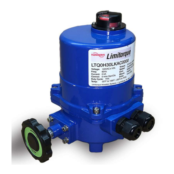
LTQ0x3 – LTQ0x4 Series User Instructions – AIIOM000166 EN 3 Product Description 3.1 General Product Description 3.1.1 LTQ008 – LTQ230 The LTQ0x3 – LTQ0x4 Series are quarter-turn, electric industrial service actuators delivering up to 440 in-lb of torque with voltages ranging from 12VAC/DC to 230V single-phase with on/off or proportional control modes. These NEMA 4X and IP67 compliant units are equipped with two volt-free Form A auxiliary switches rated at, up to, 3A 24V, and a standard clutch-free, manual-override handwheel. -
Page 11: Rotation Of Components
LTQ0x3 – LTQ0x4 Series User Instructions – AIIOM000166 EN 3.2 Rotation of Components Output drive rotation: All LTQ0x3 Series actuators rotate CW to move from 90° to 0°. So, when viewed from above, the output shaft (out the bottom of the actuator) will drive CW to 0º when performing the command. -
Page 12: Installation
All terminals accept 14 – 18 AWG solid / stranded wire. - Do not parallel wire multiple on / off actuators together without utilizing isolation relays. If this is the plan, contact Flowserve for a multiple actuator parallel wiring diagram. Page 11 of 46... -
Page 13: Theory Of Operation
LTQ0x3 – LTQ0x4 Series User Instructions – AIIOM000166 EN 5 Theory of Operation 5.1 NCU On/Off Control 1. Starting with the most basic design are the NCU Series actuators. These models are designed for use with existing single-phase installations where motor control centers are already established. a. -
Page 14: Ncu Proportional Control
LTQ0x3 – LTQ0x4 Series User Instructions – AIIOM000166 EN 5.2 NCU Proportional Control 1. These models are designed to be used where there are no existing MCCs. Typically, these are used in new facilities, or where additions to existing switch gears have available space limitations or is otherwise just not feasible. -
Page 15: Control Station On/Off Controls
LTQ0x3 – LTQ0x4 Series User Instructions – AIIOM000166 EN 5.3 Control Station On/Off Controls LTQ advanced stand-alone actuators are designed to be installed in new construction sites or existing sites where there are NO existing local control capabilities. These single phase and low voltage actuators have several versions that continue to add more features and options than the standard actuator range. -
Page 16: Control Station Proportional Controls
LTQ0x3 – LTQ0x4 Series User Instructions – AIIOM000166 EN 5.4 Control Station Proportional Controls LTQ LB advanced stand-alone actuators are designed to be installed in new construction sites or existing sites where there are NO existing local control capabilities. These single phase and low voltage actuators have several versions that continue to add more features and options than the standard actuator range. -
Page 17: Lk Series Lcs Operation
LTQ0x3 – LTQ0x4 Series User Instructions – AIIOM000166 EN 5.5 LK series LCS Operation This round NEMA 4X & IP65 enclosure houses two rotary control switches that provide the user with the ability to operate the actuator in a normal (REMOTE) mode where the actuator responds to control signals from a building automation system or a PLC or other control device (by others). -
Page 18: Lb Series Lcs Operation
LTQ0x3 – LTQ0x4 Series User Instructions – AIIOM000166 EN 5.6 LB series LCS Operation This round NEMA 4X & IP67 enclosure houses two rotary control knobs that provide the user with the ability to operate the actuator in a normal (REMOTE) mode where the actuator responds to control signals from a building automation system or a PLC or other control device (by others). -
Page 19: Battery Backup
LTQ0x3 – LTQ0x4 Series User Instructions – AIIOM000166 EN 6 Battery Backup 6.1 Battery Identification The LTQ003-004 Series Battery Backup units are fitted with a battery storage enclosure mounted directly onto the actuator as shown. All wiring for the battery pack is complete and an internal disconnect for the battery system is provided. - Do NOT install battery backup units in direct sunlight. -
Page 20: 120/230V Transformer Mounting And Setup
LTQ0x3 – LTQ0x4 Series User Instructions – AIIOM000166 EN 6.2 120/230V Transformer Mounting and Setup Power Supply: The LTQ0x3 & 0x4 Series Battery Backup units require a 100VA 24vac / 5A 24vdc power supply directly into the actuator terminal block. To facilitate various site power availability, an optional enclosure is offered which houses an appropriately sized toroidal transformer to supply the 24V power to the actuator. -
Page 21: Adjustments
LTQ0x3 – LTQ0x4 Series User Instructions – AIIOM000166 EN 7 Adjustments This actuator arrives calibrated and tested by the factory to stop at 0° for the CW position and 90° for the CCW position. Most installations onto valves or dampers will likely not require recalibration of these settings. Mount the valve or damper. -
Page 22: Auxiliary Switch Cam Mapping
LTQ0x3 – LTQ0x4 Series User Instructions – AIIOM000166 EN Adjusting End-of-Travel Cams , and 7.1.3, Adjusting Auxiliary Switch Cams. Otherwise, proceed without adjusting the cams. For most actuators, the stop positions are independent of one another – e.g., the CW position is accurate while the CCW position may need adjustment. -
Page 23: Adjusting End-Of-Travel Cams
LTQ0x3 – LTQ0x4 Series User Instructions – AIIOM000166 EN 7.2 Adjusting End-of-Travel Cams - Allowing the motor to drive the gear train beyond its 0 – 90° travel arc will result in severe damage to the actuator! Remove power from this device before making any travel adjustments. -
Page 24: Adjusting Auxiliary Switch Cams
LTQ0x3 – LTQ0x4 Series User Instructions – AIIOM000166 EN 7.3 Adjusting Auxiliary Switch Cams - Allowing the motor to drive the gear train beyond its 0 – 90° travel arc will result in severe damage to the actuator! Remove power from this device before making any travel adjustments. -
Page 25: Proportional Control Setup
LTQ0x3 – LTQ0x4 Series User Instructions – AIIOM000166 EN 7.4 Proportional Control Setup During the initial setup, before changing the actuator rotation, ensure that the sector gear set screws (qty 2) are loose enough to allow the sector gear / potentiometer pinion gear to rotate freely by hand. -
Page 26: Manual Override
LTQ0x3 – LTQ0x4 Series User Instructions – AIIOM000166 EN With the sector gear set screws loosened as described, lift the sector gear so it is not meshed with the pinion gear. Place the actuator gear train in the fully CW (0°) position. ... -
Page 27: On/Off Control
LTQ0x3 – LTQ0x4 Series User Instructions – AIIOM000166 EN operation using the following procedure. However, if the cam positions require changes, refer to section 7 Error! Reference source not found.. - Follow these directions carefully and in order. Actuator damage due to improper testing and commissioning will not be covered under the warranty. -
Page 28: Lk/Lb On/Off Controls
LTQ0x3 – LTQ0x4 Series User Instructions – AIIOM000166 EN 12. The actuator stops at 50% travel and feedback measures 12 mA (6 VDC) ± tolerance error if any (single decimal). 13. Return Field control to automatic mode. 14. The actuator is now commissioned and operational. 8.3 LK/LB On/Off Controls 1. -
Page 29: Battery Backup On/Off Control
LTQ0x3 – LTQ0x4 Series User Instructions – AIIOM000166 EN b. Re-apply power. The actuator will move CCW. After confirmation, remove the jumper and re-connect field wiring to terminal 6. 13. Generate a remote CCW move command and confirm the DIRECTION of the position indicator is CCW. a. -
Page 30: Calibration Procedures
7 Adjustments before proceeding. - Identify your actuator and follow these model-specific directions carefully and in order. The Flowserve warranty does not cover actuator damage due to improper testing and commissioning. 9.2 On/Off Control Apply correct power according to the actuator model. - Page 31 LTQ0x3 – LTQ0x4 Series User Instructions – AIIOM000166 EN 6. Make the field wiring connections for power, control, and feedback signals, referencing the proper wiring diagrams. a. Connections are made to the main terminal block only. b. No connections are made to the proportional control board directly. 7.
- Page 32 LTQ0x3 – LTQ0x4 Series User Instructions – AIIOM000166 EN Figure 27: Proportional control board for 120 – 230 VAC models Page 31 of 46...
-
Page 33: Proportional Control For 12 - 24 Vac/Vdc Models
LTQ0x3 – LTQ0x4 Series User Instructions – AIIOM000166 EN 9.4 Proportional Control for 12 – 24 VAC/VDC Models After completing all mounting and wiring procedures, and main power is available, it is now possible to calibrate the actuator. Reference Figure for the following steps. Before applying power or making any wiring connections: 1. - Page 34 LTQ0x3 – LTQ0x4 Series User Instructions – AIIOM000166 EN Figure 29: Proportional control board for 12 – 24 VAC/VDC models Page 33 of 46...
-
Page 35: Calibration Procedure For On/Off With Battery Backup
LTQ0x3 – LTQ0x4 Series User Instructions – AIIOM000166 EN 9.5 Calibration Procedure for On/Off with Battery Backup - Follow these directions carefully and in order. Actuator damage due to improper testing and commissioning will NOT be covered under warranty. After completing all mounting and wiring procedures and main power is available, it is now possible to commission the actuator. - Page 36 LTQ0x3 – LTQ0x4 Series User Instructions – AIIOM000166 EN Figure 31: Battery Backup Open/Close PCB details Page 35 of 46...
-
Page 37: Troubleshooting
If problems still exist after consulting Table and Table , contact Flowserve for additional support. Table 3: Fault symptoms for on/off control models T h e a c t u a t o r d o e s n o t m o v e w h e n c o m m a n d e d t o d o s o . - Page 38 LTQ0x3 – LTQ0x4 Series User Instructions – AIIOM000166 EN Table 4: Fault symptoms for proportional control models T h e a c t u a t o r d o e s n o t m o v e w h e n c o m m a n d e d t o d o s o . ...
- Page 39 LTQ0x3 – LTQ0x4 Series User Instructions – AIIOM000166 EN Table 5: Fault symptoms for failsafe control models A c t u a t o r d o e s n o t m o v e t o e x p e c t e d F a i l - S a f e p o s i t i o n u p o n l o s s o f m a i n s p o w e r ...
-
Page 40: Technical Data
LTQ0x3 – LTQ0x4 Series User Instructions – AIIOM000166 EN 11 Technical Data 11.1 Nameplate Page 39 of 46... -
Page 41: Torque Requirements
LTQ0x3 – LTQ0x4 Series User Instructions – AIIOM000166 EN 11.2 Torque Requirements Table 2: LTQ0H3 – LTQ0H4 actuator specifications Actuator LTQ0x3 LTQ0x4 Supply Torque Output (in-lb / N m) 310 / 35 440 / 50 Current Draw (Start/Run/LRA) 3.5A / 2.0A / 3.8A 3.5A / 2.0A / 3.8A Speed (90°) DC-60Hz / 50Hz, seconds 8 / 8... -
Page 42: Wire Sizing
LTQ0x3 – LTQ0x4 Series User Instructions – AIIOM000166 EN 11.3 Wire Sizing - To avoid dangerous or fatal electrical shock, turn off the power to all electrical equipment before working on electrical connections. Table 7: Maximum distance between the actuator and the power supply (ft) Actuator LTQ0H3 –... -
Page 43: Ltq 0H3/4 Exploded View
LTQ0x3 – LTQ0x4 Series User Instructions – AIIOM000166 EN 11.4 LTQ 0H3/4 Exploded View Page 42 of 46... -
Page 44: Ltq 0H3/4 Lk/Lb Exploded View
LTQ0x3 – LTQ0x4 Series User Instructions – AIIOM000166 EN 11.5 LTQ 0H3/4 LK/LB Exploded View Page 43 of 46... -
Page 45: Annex A: Glossary
LTQ0x3 – LTQ0x4 Series User Instructions – AIIOM000166 EN Annex A: Glossary Below are terms and definitions used throughout this manual: XTS denotes a product manufactured without Torque Switches. TS denotes a product manufactured with Torque Switches. XFS denotes a product manufactured without Fail Safe built-in. FS denotes a product manufactured with Fail Safe built-in. - Page 46 LTQ0x3 – LTQ0x4 Series User Instructions – AIIOM000166 EN (Intentionally blank page, author should remove the text in the parenthesis before publishing the document; remove this page if the back page is not printed correctly) Page 45 of 46...
- Page 47 Flowserve Corporation has established industry leadership in the design and manufacture of its products. When properly selected, this Flowserve product is designed to perform its intended function safely during its useful life. However, the purchaser or user of Flowserve products should be aware that Flowserve product might be used in numerous application under a wide variety of industrial service conditions.