Sign In
Upload
Manuals
Brands
Flowserve Manuals
Controller
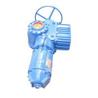
Limitorque L120-2000
User Manuals: Flowserve Limitorque L120-2000 Actuator
Manuals and User Guides for Flowserve Limitorque L120-2000 Actuator. We have
1
Flowserve Limitorque L120-2000 Actuator manual available for free PDF download: User Instructions
Flowserve Limitorque L120-2000 User Instructions (56 pages)
Brand:
Flowserve
| Category:
Controller
| Size: 2 MB
Table of Contents
Table of Contents
3
Introduction
5
Purpose
5
User Safety
5
Initial Inspection and Storage Instructions
6
Product Identification
7
Inspection and Recording
8
Short-Term Storage (Less than 1 Year)
8
Figure 2.1 - L120-190 through 2000
8
Actuator Weights
10
Table 3.1 - Actuator Weights
10
Installation Instructions
11
Safety Precautions
11
Safety Practices
12
Actuator Preparation
12
Mounting Base
13
Stem Acceptance
13
Double Torque Switch
13
Figure 4.1 - Double Torque Switch
13
Table 4.1 - Mounting Base Dimensions
13
Table 4.2 - Maximum Stem Acceptance
13
Setting Torque Switch
14
Figure 4.2 - Setting Torque Switch
14
Balancing Torque Switch
15
Torque Switch Terminal Connections
15
Figure 4.3 - Ring Tongue Terminal
15
Geared Limit Switch - Rotor Type
16
Setting Limit Switch
16
Table 4.3 - Terminal Dimensions by Cable Size
16
Figure 4.4 - Geared Limit Switch
17
Table 4.4 - Maximum Drive Sleeve Turns
17
Figure 4.5 - Setting Geared Limit Switch
18
Combination of Contacts
19
Position Indication
19
Local Position Indication
19
Figure 4.6 - Position Indicators
19
Remote Position Indication
20
Calibrating Position Transmitter PT20SD
20
Figure 4.7 - Typical Connection for a 1000 Ohm Potentiometer
20
Operation
21
Electrical Start-Up
21
Typical Wiring Diagram
22
Manual Operation
22
Motor Operation
23
Torque and Travel Limiting
23
Maintenance
24
Lubrication
24
Lubrication Inspection
24
Factory Lubricant
25
Table 6.1 - Lubricant Weights
25
Disassembly and Reassembly
26
L120-190, -420, and -800
26
To Replace Stem Nut Only
26
L120-190, 420, 800 Disassembly
27
Reassembling Actuator Sizes L120-190, -420 and -800
28
Gaskets
29
Figure 7.1 - L120-190 and -420 Drive Sleeve Side View (Refer to Table 8.1 for Parts List)
30
Figure 7.2 - L120-190 and -420 Worm Shaft Side View (Refer to Table 8.1 for Parts List)
31
Figure 7.3 - L120-190 and -420 Top View (Refer to Table 8.1 for Parts List)
32
Figure 7.4 - L120-800 Drive Sleeve Side View (Refer to Table 8.1 for Parts List)
33
Figure 7.5 - L120-800 Worm Shaft Side View (Refer to Table 8.1 for Parts List)
34
Figure 7.6 - L120-800 Top View (Refer to Table 8.1 for Parts List)
35
Table 7.1 - L120-190, -420 and -800 Typical Parts List
36
L120-2000
38
Drive 2 Disassembly (Thrust Housing Only)
38
Drive 1 (Torque Housing) Reassembly
40
Drive 2 (Thrust Housing Only) Reassembly
42
Figure 7.7 - L120-2000 Drive Sleeve Side View (Torque Base) (Refer to Table 8.2 for Parts List)
43
Figure 7.8 -L120-2000 Top View (Refer to Table 8.2 for Parts List)
44
Figure 7.9 - L120-2000 Side View (Refer to Table 8.2 for Parts List)
45
Figure 7.10 - L120-2000 Exploded View
46
Table 7.2 - L120-2000 Typical Parts List
47
Standard Wiring Diagrams
49
Figure 8.1 - Wiring Diagram - no Controls
49
Figure 8.2 - Wiring Diagram - Integral Controls
50
Figure 8.3 - Wiring Diagram - NCU
51
Troubleshooting
52
How to Order Parts
53
EC Declaration of Conformity
54
Advertisement
Advertisement
Related Products
Flowserve Limitorque L120 Series
Flowserve Limitorque L120-10
Flowserve Limitorque L120-40
Flowserve Limitorque L120-85
Flowserve Limitorque L120-190
Flowserve Limitorque L120-420
Flowserve Limitorque L120-800
Flowserve LMENIM5001-02
Flowserve LTQ008 Series
Flowserve LTQ034
Flowserve Categories
Control Unit
Water Pump
Controller
Valve Positioners
Racks & Stands
More Flowserve Manuals
Login
Sign In
OR
Sign in with Facebook
Sign in with Google
Upload manual
Upload from disk
Upload from URL