
Related Manuals for Flowserve Limitorque L120-85


Summary of Contents for Flowserve Limitorque L120-85
- Page 1 USER INSTRUCTIONS Limitorque L120-85 Actuator Installation ® Operation FCD LMENIM1202-03-A4 – 06/15 Maintenance Experience In Motion...
-
Page 2: Table Of Contents
Limitorque L120-85 Installation, Operation and Maintenance FCD LMENIM1202-03-A4 – 06/15 Contents Introduction Maintenance Purpose Lubrication User Safety 6.1.1 Initial Inspection Initial Inspection and Storage Instructions 6.1.2 Frequency Inspection and Recording 6.1.3 Routine Inspection Short-Term Storage 6.1.4 Factory Lubricants Product Identification 6.1.5... - Page 3 Limitorque L120-85 Installation, Operation and Maintenance FCD LMENIM1202-03-A4 – 06/15 Figures Tables Figure 1: Limitorque L120-85 Actuator Table 1: L120-85 Approximate Weight Chart Figure 2: L120-85 Torque Drive Nut and Retaining Ring Details Table 2: Torque Drive Nut: Maximum Allowable...
-
Page 4: Introduction
Information is provided for installation, disassembly, reassembly, lubrication, and parts selection. WARNING: Read this installation and maintenance manual carefully and completely before storing, installing, operating or troubleshooting your Flowserve Limitorque actuator. Be aware of electrical hazards within the actuator and high-pressure hazards at the attached valve or other device when installing or performing maintenance on your L120-85 actuator. -
Page 5: Initial Inspection And Storage Instructions
Limitorque L120-85 Installation, Operation and Maintenance FCD LMENIM1202-03-A4 – 06/15 Initial Inspection and Storage Instructions 2.1 Inspection and Recording Upon receipt of the actuator, several steps should be initially followed to ensure condition of equipment and to establish proper record keeping. -
Page 6: Product Identification
Limitorque L120-85 Installation, Operation and Maintenance FCD LMENIM1202-03-A4 – 06/15 2.3 Product Identification The actuator nameplate is located on the back of the actuator, opposite the limit switch compartment. The nameplate contains the following information: • Product name • Point of Manufacture •... -
Page 7: Product Description
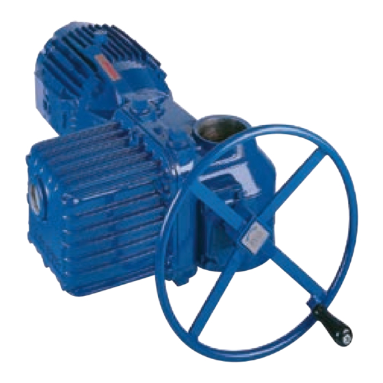
Limitorque L120-85 Installation, Operation and Maintenance FCD LMENIM1202-03-A4 – 06/15 Figure 1: Limitorque L120-85 Actuator Declutch Lever Conduit Openings (plugged; two additional openings are supplied on the bottom of the Electrical Compartment) Housing Motor Position Indication Window Handwheel Electrical Compartment... -
Page 8: Actuator Weight
Limitorque L120-85 Installation, Operation and Maintenance FCD LMENIM1202-03-A4 – 06/15 Actuator Weight The following table is an L120-85 representative weight chart. It provides the weight of several components that may be incorporated into a typical package. Use the chart as a guideline to estimate the weight of your particular actuator package. -
Page 9: Installation Instructions
Limitorque L120-85 Installation, Operation and Maintenance FCD LMENIM1202-03-A4 – 06/15 Installation Instructions WARNING: Read this Installation and Maintenance Manual carefully and completely before attempting to store, install, operate or troubleshoot your Limitorque valve actuator. Be aware of electrical hazards within the actuator and high pressure hazards of the attached valve or other actuated device when installing or performing maintenance on your L120-85 actuator. -
Page 10: Figure 2: L120-85 Torque Drive Nut And Retaining Ring Details
Limitorque L120-85 Installation, Operation and Maintenance FCD LMENIM1202-03-A4 – 06/15 4.1.1 Torque Only Applications (Drive 1) (Refer to Figure 27) Remove the Torque Nut Retaining Ring (piece 98) and Torque Drive Nut (piece 95) from actuator. Figure 2: L120-85 Torque Drive Nut and Retaining Ring Details... -
Page 11: Torque Only Applications (Drive 1)
Limitorque L120-85 Installation, Operation and Maintenance FCD LMENIM1202-03-A4 – 06/15 A) If the Thrust Base Drive Sleeve (piece 101) has been threaded by supplier, verify thread compatibility with the threaded Valve Stem by screwing Drive Sleeve onto the valve stem. -
Page 12: Verifying Motor Rotation Direction
Limitorque L120-85 Installation, Operation and Maintenance FCD LMENIM1202-03-A4 – 06/15 B. Torque and Thrust Applications (Drive 2) Screw the Thrust Base Assembly onto the Threaded Valve Stem and secure the Thrust Base Assembly to the Actuator Mounting Base using Socket Head Cap Screws (piece 110) and Lockwashers (piece 111). -
Page 13: Figure 6: Electrical Compartment And Conduit Pipe Plug Openings
Limitorque L120-85 Installation, Operation and Maintenance FCD LMENIM1202-03-A4 – 06/15 Open the Electrical Compartment Cover (piece 200-1) and remove the Conduit Pipe Plugs from the opening(s) most conveniently located for your power leads and other cabling. Conduit Pipe Plug Locations... -
Page 14: Motor Rotation (Phasing) And Open/Close Pushbutton Operation
Limitorque L120-85 Installation, Operation and Maintenance FCD LMENIM1202-03-A4 – 06/15 Inspect actuator for proper lubrication. Refer to “Lubrication” Section 6.1 for lubrication instructions. Verify that Motor rotation is operating in the proper direction; the Motor rotation will have a direct impact on the Limit Switch and Torque Switch functions. -
Page 15: Limit Switch Settings
Limitorque L120-85 Installation, Operation and Maintenance FCD LMENIM1202-03-A4 – 06/15 4.3 Limit Switch Settings The standard L120-85 Limit Switch has 16 contacts. The OPEN/CLOSE Limit Switch (first eight contacts) has two Rotor Sets, one for the OPEN position and one for the CLOSED position. Each Rotor Set has four electrical contacts which can be arranged in any combination of normally OPEN and normally CLOSED. -
Page 16: Adjustment-General
Limitorque L120-85 Installation, Operation and Maintenance FCD LMENIM1202-03-A4 – 06/15 The OPEN Rotor consists of contacts 1 through 4. These switches are set to change state at the full OPEN position. The switch functions are as follows: Contact 1 is the CLOSED Torque Switch bypass circuit. It’s purpose is to allow the electric actuator to apply its full torque to unseat a backseated valve. -
Page 17: Setting The Open Limit Switch
Limitorque L120-85 Installation, Operation and Maintenance FCD LMENIM1202-03-A4 – 06/15 CAUTION: The Worm on the Worm Shaft Assembly is available in two different ratios 19:1 and 38:1. To avoid damage to the gearing mechanisms, be sure you change the Limit Switch Drive Pinion gear if the Worm gear ratio is changed. -
Page 18: Setting The Close Limit Switch
Limitorque L120-85 Installation, Operation and Maintenance FCD LMENIM1202-03-A4 – 06/15 CAUTION: For highly geared actuators, one turn of the handwheel may not be sufficient to allow for coast of moving parts. Refer to valve manufacturer setting requirements in these cases. -
Page 19: Torque Switch Setting And Wiring
Limitorque L120-85 Installation, Operation and Maintenance FCD LMENIM1202-03-A4 – 06/15 NOTE: Most applications require turning the Handwheel CW to obtain the full CLOSE position and CCW to obtain full OPEN position. The actuator Drive Sleeve rotates in a CW direction to the CLOSE position and CCW to the OPEN position. -
Page 20: Basic Theory Of Operation
Limitorque L120-85 Installation, Operation and Maintenance FCD LMENIM1202-03-A4 – 06/15 4.4.1 Basic Theory of Operation As torque is developed by the actuator, the Worm moves axially and causes compression on the Spring Pack Assembly (components of the Worm Shaft Assembly (piece 15)). The Spring Pack Assembly is calibrated so that a given amount of spring compression equates to a given amount of output torque. -
Page 21: Rewiring The Torque Switch For Non-Standard Drive Sleeve Rotation
Limitorque L120-85 Installation, Operation and Maintenance FCD LMENIM1202-03-A4 – 06/15 Ensure that the actuator is in MANUAL mode and the load is removed from the Worm Shaft Assembly. Make note of the current OPEN and CLOSED Torque Switch settings before reinstalling the Torque Switch. -
Page 22: Position Indication
Limitorque L120-85 Installation, Operation and Maintenance FCD LMENIM1202-03-A4 – 06/15 Remove the Mechanical Dial Position Indicator Plate and flip over for indication of CCW rotation to the valve’s CLOSED position. See figure 13 for MDPI Dial Plate. Reverse the OPEN/CLOSE directional arrow on the Handwheel. -
Page 23: Figure 14: Remote Position Indicator Calibration Configuration
Limitorque L120-85 Installation, Operation and Maintenance FCD LMENIM1202-03-A4 – 06/15 Mount the Adjustable Resistor as close as possible to the Remote Voltmeter Indicator. Turn power to the actuator OFF and connect all wiring as shown in Figure 14. For now, connect the wires leading to the Remote Voltmeter Indicator to your test meter so you can conduct voltage readings during the setup. -
Page 24: Setting The Potentiometer
Limitorque L120-85 Installation, Operation and Maintenance FCD LMENIM1202-03-A4 – 06/15 4.5.3 Setting the Potentiometer If your L120-85 actuator includes a Feedback Potentiometer supplied for remote valve position indication, use an ohmmeter to calibrate the position of the Potentiometer. Typically, the Potentiometer Spur Gear is shipped from the factory dis-engaged from the Potentiometer Drive Gear. -
Page 25: Figure 16: Loosening Potentiometer Assembly
Limitorque L120-85 Installation, Operation and Maintenance FCD LMENIM1202-03-A4 – 06/15 Figure 16: Loosening Potentiometer Assembly Hex Head Retaining Nut Pontentiometer Spur Gear Pontentiometer Drive Gear If the Potentiometer Spur Gear is not engaged with the Potentiometer Drive Gear continue to step 7. -
Page 26: Operation
Limitorque L120-85 Installation, Operation and Maintenance FCD LMENIM1202-03-A4 – 06/15 Operation L120-85 actuators are always available for motor operation when the motor is energized. Do not force the Declutch Lever into the motor operation position. The Declutch Lever returns to motor operation position automatically when the motor is energized. -
Page 27: Electrical Start-Up Procedure
Limitorque L120-85 Installation, Operation and Maintenance FCD LMENIM1202-03-A4 – 06/15 the Declutch Shaft which is keyed to the Declutch Link (piece 7-1). The Declutch Link engages the Clutch Ball Bearing (piece 19-2) which disengages the Clutch from the Motor Cam and engages the Handwheel Lugs (piece 3-1). The Clutch Latches (piece 32) hold the Clutch Assembly in MANUAL operation until the Motor is energized. -
Page 28: Maintenance
Limitorque L120-85 Installation, Operation and Maintenance FCD LMENIM1202-03-A4 – 06/15 Maintenance 6.1 Lubrication 6.1.1 Initial Inspection NOTE: Before operating your actuator, inspect it for proper lubrication, (especially if it has been stored for a long period of time). No seal can remain absolutely tight at all times; therefore, it is not unusual to find a very small amount of weeping around shaft seals —... -
Page 29: Factory Lubricants
Limitorque L120-85 Installation, Operation and Maintenance FCD LMENIM1202-03-A4 – 06/15 6.1.4 Factory Lubricants Gear Case • L120-85 is factory lubricated with an EP-0 lithium base grease, suitable for temperatures from -20°F (-29°C) to + 250°F (+121°C). Geared Limit Switch: Exxon Beacon 325 (no substitute). -
Page 30: Disassembly
Limitorque L120-85 Installation, Operation and Maintenance FCD LMENIM1202-03-A4 – 06/15 Disassembly WARNING: Hazardous Voltage. Turn power OFF before disassembling your L120-85 actuator. WARNING: Potential high pressure vessel. Before removing or disassembling your actuator, ensure that the valve or other actuated device is isolated and is not under pressure. -
Page 31: Open Electrical Compartment And Disconnect Motor
Limitorque L120-85 Installation, Operation and Maintenance FCD LMENIM1202-03-A4 – 06/15 b. Lift actuator completely off of the Mounting Adapter or Thrust Base Assembly. c. Disconnect Motor and remove control wiring (see next two sections). d. Drive 2 Only: Rotate the Thrust Base Assembly off the threaded Valve Stem. -
Page 32: Remove Declutch Lever Assembly
Limitorque L120-85 Installation, Operation and Maintenance FCD LMENIM1202-03-A4 – 06/15 7.8 Remove Declutch Lever Assembly Before removing the Declutch Lever Assembly (piece 9), loosen Hex Head Screws and Lockwashers (piece #s 50-5 and 50-6) and rotate the Declutch Lever Stop Plate (piece 11) in the CW direction to free the Declutch Lever Assembly. -
Page 33: Remove And Disassemble Thrust Base
Limitorque L120-85 Installation, Operation and Maintenance FCD LMENIM1202-03-A4 – 06/15 Push the Worm Shaft Assembly through the opposite end of the actuator. The Worm Shaft Assembly is comprised of Worm Shaft (piece 15-1), Worm (piece 15-2), Ball Bearing (piece 15-3), Ball Bearing (piece 15-4), Disc Spring (piece 15-5-1), Spring Pack... -
Page 34: Assembly
Limitorque L120-85 Installation, Operation and Maintenance FCD LMENIM1202-03-A4 – 06/15 Assembly Assembly should be conducted in the reverse order of the disassembly procedures noting the following points: 8.1 Handwheel Shaft Assembly and Shimming If you have disassembled the Clutch Latch Assembly (pieces 32-1, 32-2 and 33) or have replaced the... -
Page 35: Figure 19: Cut-Away View Of L120-85 Actuator
Limitorque L120-85 Installation, Operation and Maintenance FCD LMENIM1202-03-A4 – 06/15 Before shimming the Handwheel Assembly and to assure proper Handwheel Lug (piece 3-1) engagement with the Clutch (piece 19-1), push the Declutch Lever into the MANUAL mode until Latch 32-1 is engaged with Clutch Bearing (piece 19-2) as shown in figures 18 and 19. -
Page 36: Table 4: Gap "A" Shim Thickness Selection Chart
Limitorque L120-85 Installation, Operation and Maintenance FCD LMENIM1202-03-A4 – 06/15 Select a shim thickness to satisfy the following chart (each shim is .030"): Table 4: Gap “A” shim thickness selection chart Shim Thickness for Gap “A” Dimension “A” Nominal shim thickness at gap “A”... -
Page 37: Figure 21: Shimming Parts And Their Order Of Assembly
Limitorque L120-85 Installation, Operation and Maintenance FCD LMENIM1202-03-A4 – 06/15 Figure 21: Shimming parts and their order of assembly #44 O-ring #43 O-ring #4-1 Handwheel (not shown) Bushing #52 Handwheel Shaft Washer #6-1 & 6-2 Shims #4-2 Handwheel #6-1 & 6-2 Remaining Shims Spacer Figure 22: Shim location for gap “B”... -
Page 38: Verifying Handwheel Operation
Limitorque L120-85 Installation, Operation and Maintenance FCD LMENIM1202-03-A4 – 06/15 8.2 Verifying Handwheel Operation After your actuator is completely assembled, test the Handwheel for MANUAL operation. Put the Declutch Lever in MANUAL mode, turn the Handwheel in either direction to ensure MANUAL operation is turning the Drive Sleeve mechanism. If there is resistance to turning the Handwheel, the Declutch Lever Assembly is not properly disengaging the Motor Cam from the Clutch Pinion Assembly. -
Page 39: Troubleshooting
Limitorque L120-85 Installation, Operation and Maintenance FCD LMENIM1202-03-A4 – 06/15 Troubleshooting WARNING: Be aware of electrical and high-pressure hazards when troubleshooting or performing maintenance on your L120-85 actuator. Symptom Possible Cause Corrective Action Actuator will not operate electrically 1. No power to actuator 1a. - Page 40 Limitorque L120-85 Installation, Operation and Maintenance FCD LMENIM1202-03-A4 – 06/15 Symptom Possible Cause Corrective Action Fuse blown 1. Incorrect fuse size 1. Verify fuses are sized correctly. 2. Pinched wire 2. Inspect control compartment to ensure Control Cover is not pinching or making contact with wiring when installed.
-
Page 41: Typical Wiring Diagram
Limitorque L120-85 Installation, Operation and Maintenance FCD LMENIM1202-03-A4 – 06/15 9.1 Typical Wiring Diagram Three-phase with Control Package The wiring diagram below is a representation of a typical application and may not be applicable to your specific actuator. Please refer to the wiring diagram supplied with your actuator to confirm the actual equipment supplied. -
Page 42: How To Order Parts
Limitorque L120-85 Installation, Operation and Maintenance FCD LMENIM1202-03-A4 – 06/15 How to Order Parts To obtain further information or order parts for your Limitorque valve actuator, contact your local Limitorque distributor, sales office or contact: Flowserve Limitorque 5114 Woodall Road P.O. -
Page 43: L120-85 Illustrated Parts Breakdown
Limitorque L120-85 Installation, Operation and Maintenance FCD LMENIM1202-03-A4 – 06/15 10.1 L120-85 Illustrated Parts Breakdown Figure 24: Electrical Compartment 305-48 305-47 Heater Bracket Grounding Lug Kit 300-21 300-20 300-27 200-3 200-2 200-1 flowserve.com... -
Page 44: Figure 25: Motor And Motor Drive Components
Limitorque L120-85 Installation, Operation and Maintenance FCD LMENIM1202-03-A4 – 06/15 Figure 25: Motor and Motor Drive Components 18-3 (not shown) 18-2 18-1 50-26 Clutch Pinion 50-25 Assembly (18 ) 50-3 50-4 31-1 50-7 31-2 Motor Leads 42-3 19-2 19-3 32-1... -
Page 45: Figure 26: Handwheel Shaft And Associated Components
Limitorque L120-85 Installation, Operation and Maintenance FCD LMENIM1202-03-A4 – 06/15 Figure 26: Handwheel Shaft and Associated Components 50-5 50-6 42-6 29-2E 29-1A 29-1B 29-1C 29-2B 29-1D 29-2A 29-2D 29-2C 182-1 182-2 Handwheel 182-3 Sha ft A sse mbl y 42-4... -
Page 46: Figure 27: Drive Sleeve Group
Limitorque L120-85 Installation, Operation and Maintenance FCD LMENIM1202-03-A4 – 06/15 Figure 27: Drive Sleeve Group 50-24 50-24 42-1 42-2 50-16 50-2 50-1 42-5... -
Page 47: Figure 28: Thrust Base Group
Limitorque L120-85 Installation, Operation and Maintenance FCD LMENIM1202-03-A4 – 06/15 Figure 28: Thrust Base Group flowserve.com... -
Page 48: L120-85 Parts List
Limitorque L120-85 Installation, Operation and Maintenance FCD LMENIM1202-03-A4 – 06/15 10.2 L120-85 Parts List Piece Description Quantity Piece Description Quantity Unit Housing 18-3 Clutch Pinion Retaining Ring* (not shown) Handwheel Shaft 19-1 Clutch Handwheel Shaft Key 19-2 Clutch Assy. Ball Bearing... - Page 49 Limitorque L120-85 Installation, Operation and Maintenance FCD LMENIM1202-03-A4 – 06/15 Piece Description Quantity Piece Description Quantity O-ring Thrust Base Plate Pipe Plug Thrust Bearing O-ring Thrust Washer Retaining Ring O-ring Spring Retaining Washer Quad Ring 50-1 Socket Head Cap Screw...
- Page 50 Limitorque L120-85 Installation, Operation and Maintenance FCD LMENIM1202-03-A4 – 06/15 EC Declaration of Conformity...
- Page 51 Limitorque L120-85 Installation, Operation and Maintenance FCD LMENIM1202-03-A4 – 06/15 flowserve.com...
- Page 52 Fax: 91-80-28410286 its intended function safely during its useful life. However, the purchaser or user of Flowserve products should be aware that Flowserve products might be used in numerous applications under a wide variety of industrial service conditions. Although Flowserve can (and often does) provide general guidelines, it cannot provide specific data and warnings for all possible applications.
Need help?
Do you have a question about the Limitorque L120-85 and is the answer not in the manual?
Questions and answers
Ihave an open and close feedback wires where on a L120-85 actuator do you land the wires
The open and close feedback wires connect to the Limit Switch in the actuator's Electrical Compartment. The specific wiring connections should be made according to the applicable wiring diagram located inside the Electrical Compartment of the L120-85 actuator.
This answer is automatically generated