Sign In
Upload
Manuals
Brands
Flowserve Manuals
Controller
Limitorque L120-190
Flowserve Limitorque L120-190 Manuals
Manuals and User Guides for Flowserve Limitorque L120-190. We have
1
Flowserve Limitorque L120-190 manual available for free PDF download: User Instructions
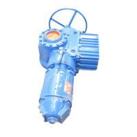
Flowserve Limitorque L120-190 User Instructions (56 pages)
Brand:
Flowserve
| Category:
Controller
| Size: 2 MB
Table of Contents
Table of Contents
3
Introduction
5
Purpose
5
User Safety
5
Initial Inspection and Storage Instructions
6
Product Identification
7
Inspection and Recording
8
Short-Term Storage (Less than 1 Year)
8
Figure 2.1 - L120-190 through 2000
8
Actuator Weights
10
Table 3.1 - Actuator Weights
10
Installation Instructions
11
Safety Precautions
11
Safety Practices
12
Actuator Preparation
12
Mounting Base
13
Stem Acceptance
13
Double Torque Switch
13
Figure 4.1 - Double Torque Switch
13
Table 4.1 - Mounting Base Dimensions
13
Table 4.2 - Maximum Stem Acceptance
13
Setting Torque Switch
14
Figure 4.2 - Setting Torque Switch
14
Balancing Torque Switch
15
Torque Switch Terminal Connections
15
Figure 4.3 - Ring Tongue Terminal
15
Geared Limit Switch - Rotor Type
16
Setting Limit Switch
16
Table 4.3 - Terminal Dimensions by Cable Size
16
Figure 4.4 - Geared Limit Switch
17
Table 4.4 - Maximum Drive Sleeve Turns
17
Figure 4.5 - Setting Geared Limit Switch
18
Combination of Contacts
19
Position Indication
19
Local Position Indication
19
Figure 4.6 - Position Indicators
19
Remote Position Indication
20
Calibrating Position Transmitter PT20SD
20
Figure 4.7 - Typical Connection for a 1000 Ohm Potentiometer
20
Operation
21
Electrical Start-Up
21
Typical Wiring Diagram
22
Manual Operation
22
Motor Operation
23
Torque and Travel Limiting
23
Maintenance
24
Lubrication
24
Lubrication Inspection
24
Factory Lubricant
25
Table 6.1 - Lubricant Weights
25
Disassembly and Reassembly
26
L120-190, -420, and -800
26
To Replace Stem Nut Only
26
L120-190, 420, 800 Disassembly
27
Reassembling Actuator Sizes L120-190, -420 and -800
28
Gaskets
29
Figure 7.1 - L120-190 and -420 Drive Sleeve Side View (Refer to Table 8.1 for Parts List)
30
Figure 7.2 - L120-190 and -420 Worm Shaft Side View (Refer to Table 8.1 for Parts List)
31
Figure 7.3 - L120-190 and -420 Top View (Refer to Table 8.1 for Parts List)
32
Figure 7.4 - L120-800 Drive Sleeve Side View (Refer to Table 8.1 for Parts List)
33
Figure 7.5 - L120-800 Worm Shaft Side View (Refer to Table 8.1 for Parts List)
34
Figure 7.6 - L120-800 Top View (Refer to Table 8.1 for Parts List)
35
Table 7.1 - L120-190, -420 and -800 Typical Parts List
36
L120-2000
38
Drive 2 Disassembly (Thrust Housing Only)
38
Drive 1 (Torque Housing) Reassembly
40
Drive 2 (Thrust Housing Only) Reassembly
42
Figure 7.7 - L120-2000 Drive Sleeve Side View (Torque Base) (Refer to Table 8.2 for Parts List)
43
Figure 7.8 -L120-2000 Top View (Refer to Table 8.2 for Parts List)
44
Figure 7.9 - L120-2000 Side View (Refer to Table 8.2 for Parts List)
45
Figure 7.10 - L120-2000 Exploded View
46
Table 7.2 - L120-2000 Typical Parts List
47
Standard Wiring Diagrams
49
Figure 8.1 - Wiring Diagram - no Controls
49
Figure 8.2 - Wiring Diagram - Integral Controls
50
Figure 8.3 - Wiring Diagram - NCU
51
Troubleshooting
52
How to Order Parts
53
EC Declaration of Conformity
54
Advertisement
Advertisement
Related Products
Flowserve Limitorque L120 Series
Flowserve Limitorque L120-10
Flowserve Limitorque L120-40
Flowserve Limitorque L120-85
Flowserve Limitorque L120-420
Flowserve Limitorque L120-800
Flowserve Limitorque L120-2000
Flowserve LTQ088
Flowserve LTQ150
Flowserve Limitorque QX
Flowserve Categories
Control Unit
Controller
Water Pump
Valve Positioners
Industrial Equipment
More Flowserve Manuals
Login
Sign In
OR
Sign in with Facebook
Sign in with Google
Upload manual
Upload from disk
Upload from URL