Sign In
Upload
Download
Table of Contents
Contents
Add to my manuals
Delete from my manuals
Share
URL of this page:
HTML Link:
Bookmark this page
Add
Manual will be automatically added to "My Manuals"
Print this page
×
Bookmark added
×
Added to my manuals
Manuals
Brands
Flowserve Manuals
Controller
Limitorque MX-10
User instructions
Flowserve Limitorque MX-10 User Instructions
Limitorque mx series electronic actuator
Hide thumbs
1
2
Table Of Contents
3
4
5
6
7
8
9
10
11
12
13
14
15
16
17
18
19
20
21
22
23
24
25
26
27
28
29
30
31
32
33
34
35
36
37
38
39
40
41
42
43
44
45
46
47
48
49
50
51
52
53
54
55
56
57
58
59
60
61
62
63
64
65
66
67
68
69
70
71
72
73
74
75
76
77
78
79
80
81
82
83
84
85
86
87
88
89
90
91
92
93
94
95
96
97
98
99
100
101
102
103
104
105
106
107
108
109
110
111
112
113
114
115
116
117
118
119
120
121
122
123
124
125
126
127
128
129
130
131
132
133
134
135
136
137
138
139
140
141
142
143
144
145
146
147
148
149
150
151
152
153
154
155
156
157
158
159
160
161
162
163
164
page
of
164
Go
/
164
Contents
Table of Contents
Bookmarks
Table of Contents
Table of Contents
1 Introduction
Premise
Procedure Emphasis
Important Notes and Warning Statements
Reference Documents
1010 MX Actuator Subassembly
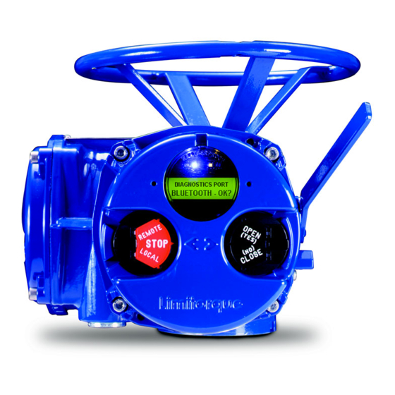
Figure 2.1 - Typical MX Actuator
MX Actuator Subassembly Components
Product Description
Storage
Table 2.1 - MX Actuator Subassembly Components
Unit Weights
Product Identification
Initial Inspection and Recording Suggestions
Figure 2.2 - MX Nameplate
Table 2.2 - Unit Weights
Maintenance
Recommended Maintenance
Unit Lubrication
Figure 2.3 - Oil Fill/Plug Locations (MX-05 through -40)
Figure 2.4 - Oil Fill and Drain Locations (MX-85, -140, and -150)
Table 2.3 - MX-05 and -10 Oil Capacities When Using Oil Fill/Plug Ports
O-Ring and Lubrication
Subassembly Removal and Remounting Procedures
How to Order Replacement Subassemblies
Replacement Parts
Return Procedure
3 Remove Actuator from Mounting Adapter
Actuator Removal with Type B1/B4/B4E Base (Torque)
Removal (Type B1/B4/B4E Base)
Remounting (Type B1/B4/B4E Base)
Actuator Removal with Type A1/A1E Base (Thrust)
Removal (Type A1/A1E Base) Actuator Removal Separate from Thrust Base
Remounting (Type A1/A1E Base) Actuator Remounting Separate from Thrust Base
Removal (Type A1/A1E Base) Actuator and Thrust Base as a Unit
Remounting (Type A1/A1E Base) Actuator and Thrust Base as a Unit
4 Mechanical Assemblies
Motor
Figure 4.1 - Motor (MX-05, -10, -20, and -40)
Table 4.1 - Motor Parts List
Removal
Remounting
Figure 4.2 - Motor and Adapter (MX-140)
Removal and Mounting of MX-140 Motor (40 RPM and Greater)
Table 4.2 - Motor Parts List
Mounting of MX-150 Motor
Remounting
Table 4.3 - Motor Parts List
Figure 4.3 - Motor, Support Plate and Adapter (MX-150)
Declutch
Figure 4.4 - Declutch (MX-05 and -10)
Table 4.4 - Declutch Parts List (MX-05 and -10)
Figure 4.5 - Declutch (MX-20 and -40)
Table 4.5 - Declutch Parts List (MX-20 and -40)
Figure 4.6 - Declutch (MX-85, -140, and -150)
Removal
Table 4.6 - Declutch Parts List (MX-85, -140, and -150)
Remounting
Top-Mounted Handwheel (MX-05, -10, -20, and -40)
Figure 4.7 - Top-Mounted Handwheel (MX-05, -10, -20, and -40)
Table 4.7 - Top-Mounted Handwheel Parts List (MX-05, -10, -20, and -40)
Remounting
Removal
Side-Mounted Handwheel Without Spur Gear Attachment (MX-10, -20, -85, -140, and -150)
Figure 4.8 - Side-Mounted Handwheel (MX-10 and -20)
Table 4.8 - Side-Mounted Handwheel Parts List (MX-10 and -20)
Figure 4.9 - Side-Mounted Handwheel (MX-85, -140, and -150)
Side-Mounted Handwheel Without Spur Gear Attachment (MX-85, -140, and -150)
Table 4.9 - Side-Mounted Handwheel Without Spur Gear Attachment Parts List (MX-85, -140, and -150)
Removal
Removal of Side-Mounted Handwheel (MX-10, -20, -85, -140, and -150)
Limitorque MX Maintenance and Spare Parts FCD LMENIM2314-00 - 07/08
Remounting
Side-Mounted Handwheel with Spur Gear Attachment (MX-40, -85, -140, and -150)
Figure 4.10 - Side-Mounted Handwheel with SGA (MX-40)
Table 4.10 - Side-Mounted Handwheel Parts List (MX-40)
Figure 4.11 - Side-Mounted Handwheel with SGA (MX-85, -140, and -150)
MX-85, -140, and -150 Handwheel with SGA
Table 4.11 - Side-Mounted Handwheel Parts List (MX-85, -140, and -150)
Removal
Removal of Handwheel
Remounting
Converting Top-Mounted Handwheel to Side-Mounted Handwheel (MX-10, -20, and -40)
Removing Top-Mounted Handwheel
Installing Side-Mounted Handwheel
Thrust Base Type A1/A1E
Figure 4.12 - Type A1 Thrust Base (MX-05, -10, -20, and -40)
Table 4.12 - Type A1 Thrust Base Parts List (MX-05, 10, -20, and -40)
Figure 4.13 - Type A1 Thrust Base (MX-85) - F16 Flange
Table 4.13 - Type A1 Thrust Base Parts List (MX-85)
Figure 4.14 - Type A1 Thrust Base (MX-85, -140, and -150) - F25 Flange
Table 4.14 - Type A1 Thrust Base Parts List (MX-85, -140, and -150) - F25 Flange
Remounting
Removal
Torque Base Type B1
Figure 4.15 - Type B1 Torque Base (MX-05, -10, -20, and -40)
Table 4.15 - Type B1 Torque Base Parts List (MX-05, -10, -20, and -40)
Remounting
Removal
Baseplate Type B4
Figure 4.16 - Type B4 Baseplate (MX-05, -10, -20, and -40)
Table 4.16 - Type B4 Baseplate Parts List
Figure 4.17 - Type B4 Baseplate (MX-85, -140, and -150)
Removal
Remounting
Worm Shaft
Figure 4.18 - Worm Shaft (MX-05, -10, -20, and -40)
Table 4.17 - Worm Shaft Parts List
Removal
Remounting
Drive Sleeve (MX-05 and -10)
Figure 4.19 - Drive Sleeve (MX-05 and -10)
Table 4.18 - Drive Sleeve Parts List (MX-05 and -10)
Removal
Remounting
Drive Sleeve (MX-20, -40, -85, -140, and -150)
Figure 4.20 - MX-20 and -40 Drive Sleeve
Table 4.19 - Drive Sleeve Parts List (MX-20, -40, -85, -140, and -150)
Figure 4.21 - MX-85, -140, and -150 10:1 and 13:1 Ratios
Removal
Figure 5.16 - Encoder
Remounting
MX-85, -140, and -150 Optional Drive Sleeve and Baseplate Removal
MX-85, -140, and -150 Optional Drive Sleeve and Baseplate Remounting
Handwheel Adapter (MX-05)
Figure 4.22 - Handwheel Adapter (MX-05)
Figure 4.23 - Handwheel (MX-05)
Table 4.20 - Handwheel Adapter Parts List (MX-05)
Removal
Remounting
Handwheel Adapter (MX-10, -20 and -40)/Handwheel Worm Gear (MX-10, -20, -40, -85, -140, and -150)
Figure 4.24 - Handwheel Adapter Assembly
Table 4.21 - Handwheel Adapter Assembly Parts List
Figure 4.25 - Handwheel Worm Gear Assembly
Table 4.22 - Handwheel Worm Gear Assembly Parts List
Removal
Remounting
Clutch and Clutch Ring Components (MX-20, -40, -85, -140, and -150)
Figure 4.26 - MX-20 and -40 Clutch and Ring Components
Figure 4.27 - MX-85, -140, and -150 Clutch and Ring Components
Table 4.23 - Clutch and Clutch Ring Components Parts List
Removal
Remounting
Figure 4.28 - MX-85, -140, and -150 Clutch Ring
Table 4.24 - Clutch Ring Assembly Parts List
5 Electronic Assemblies
Control Panel (CP)
Figure 5.1 - Control Panel
Table 5.1 - Control Panel Parts List
Control Module
Figure 5.2 - Control Module
Table 5.2 - Control Module Parts List
Removal
Remounting
Figure 5.3 - Location of Fuses and Voltage Jumper
Fuse Replacement
Control Module Return Options
EPROM Care and Replacement
Figure 5.4 - LCS Board
Figure 5.5 - Main CPU Board
Figure 5.6 - Power Board
Figure 5.7 - DDC Board
Installation and Removal of SMT Controls
(Most Units Supplied after September 2003 and before September 2007)
Installation
Removal
Fuse Replacement
Control Module Return Options
Figure 5.8 - Location of Fuses and Voltage Jumper
(Some Units Supplied from December 2006 with Majority after September 2007)
Installation
Figure 5.9 - SMT Controls with Four Leds
Table 5.3 - Voltage Jumper Positions
Removal
Mounting of Standard and Optional Controls with 54-Point Terminal Block and Four LED Configuration
Installation
Table 5.4 - Control Board Connectors
Figure 5.10 - Option Board Assembly
Table 5.5 - Screw Part Numbers
Removal
Adding Electronic Options to Your MX Actuator(most Supplied after September 2007)
Restoring Power to Actuator with New Control Module
Terminal Block (Prior to March 2007)
Figure 5.11 - Restoring Power to Actuator with New Control Module
Table 5.5 - Terminal Block Parts List
Figure 5.12 - Terminal Block
Removal
Remounting
MX Terminal Block (Supplied with most Actuators Since March 2007)
Terminal Block Shield Installation
Figure 5.13 - Terminal Block
Figure 5.14 - Terminal Block Shield
Table 5.7 - Terminal Block Parts List
Control Module-Contactor Assembly
Please See Section 5.4 for Power Board Installation with Contactor.)
Figure 5.15 - Control Module - Contactor Assembly and Wiring Diagrams
Table 5.8 - Control Module-Contactor Assembly Parts List
Removal
Figure 5.15 - (Continued)
Remounting
Replacing 19 Amp Reverser on the MX-140 and -150 (Not for most Actuators Shipped after September 2007)
Amp Power Assembly for Units Shipped after September 2007
Table 5.9 - 19 Amp Power Assembly
Encoder (through Hole and Surface Mount Technology, most Units Prior to September 2007)
Table 5.10 - Encoder Parts List
Removal
Table 5.11 - Encoder Drive Sleeve Speed (RPM)
Remounting
Encoder Drive Cartridge (most Units Prior to September 2007)
Table 5.12 - Encoder Drive Cartridge Parts List
Table 5.13 - Encoder Drive Cartridge Drive Sleeve Speed
Removal
Remounting
Removal and Replacement of MX Encoder (Supplied with most Actuators Since September 2007)
Table 5.14 - Encoder Parts List
Table 5.15 - Encoder Drive Sleeve Speed (RPM)
Remounting
Removal
Encoder Drive Cartridge (Supplied with most Actuators Since September 2007)
Figure 5.17 - Encoder Drive Cartridge
Figure 5.18 - Encoder
Figure 5.19 - Encoder Drive Cartridge
Table 5.16 - Encoder Drive Cartridge Parts List
Removal
Remounting
Motor Lead Harness (MX-85, -140, and -150)
Removal
Figure 5.20 - Motor Lead Assembly
Remounting
Solid State Motor Reverser Upgrade Instructions (most Units Prior to September 2007)
Figure 5.21 - Cutaway View of SSMR Controls Area
Table 5.17 - SSMR Upgrade Kit Parts List
Disassembly Procedure
Figure 5.22 - Disassembly Procedure
Assembly Procedure
Figure 5.23 - Solid State Reverser and Fuse Block Assembly Installation
Table 5.18 - SSMR Motor Fuse Table
Figure 5.24 - Control Module Reinstallation
Mounting of SSMR (Solid State Motor Reverser) in Units Shipped after February 2008
Table 5.19 - SSMR Parts List
Figure 5.25 - SSMR (Solid State Motor Reverser)
Complete Conversion to SMT Controls
6 Spare and Replacement Parts
Guidelines for Recommended Spare Parts
Wear Components
Bearings, O-Rings, and Seals
Critical Components
Recommended Spare Parts for MX Actuators
Commissioning and Startup
Short-Term Duty
Long-Term Duty
Severe Duty
Other Concerns
7 Regulatory Information
Declaration of Conformity
Advertisement
Quick Links
Download this manual
Swanson Flo | 800-288-7926 | www.swansonflo.com
USER INSTRUCTIONS
Limitorque MX
Maintenance
and Spare Parts
Electronic Actuator
FCD LMENIM2314-00 – 07/08
Experience In Motion
Table of
Contents
Previous
Page
Next
Page
1
2
3
4
5
Advertisement
Table of Contents
Need help?
Do you have a question about the Limitorque MX-10 and is the answer not in the manual?
Ask a question
Questions and answers
Subscribe to Our Youtube Channel
Related Manuals for Flowserve Limitorque MX-10
Controller Flowserve MX Installation, Operation, Maitenance Manual
Electronic actuator (112 pages)
Controller Flowserve Limitorque MX-40 User Instructions
Limitorque mx series electronic actuator (164 pages)
Controller Flowserve Limitorque MX-05 User Instructions
Limitorque mx series electronic actuator (164 pages)
Controller Flowserve Limitorque MX-20 User Instructions
Limitorque mx series electronic actuator (164 pages)
Controller Flowserve Limitorque Accutronix MX Mounting Instructions
Limitorque actuation systems (16 pages)
Controller Flowserve Limitorque MX Safety Manual
Electronic actuator (44 pages)
Controller Flowserve PMV D3 User Instructions
Digital positioner (56 pages)
Controller Flowserve FlowAct IG 253 Assembly Instructions Manual
(44 pages)
Controller Flowserve Limitorque QX User Instructions
Electronic (96 pages)
Controller Flowserve NAF Series Maintenance Instructions And Spare Parts List
Pneumatic (20 pages)
Controller Flowserve ARGUS E25 MOD II Installation And Operating Instructions Manual
Electric valve actuator (52 pages)
Controller Flowserve Valtek VR User Instructions
Spring cylinder rotary actuators (13 pages)
Controller Flowserve Limitorque L120 Series User Instructions
Actuation systems (36 pages)
Controller Flowserve Limitorque LTQ008 User Instructions
Maintenance compact quarter-turn electric actuator (41 pages)
Controller Flowserve Limitorque QX Maintenance And Spare Parts
(82 pages)
Controller Flowserve NORBRO 40R Series User Instructions
Pneumatic actuator (16 pages)
Table of Contents
Save PDF
Print
Rename the bookmark
Delete bookmark?
Delete from my manuals?
Login
Sign In
OR
Sign in with Facebook
Sign in with Google
Upload manual
Upload from disk
Upload from URL


Need help?
Do you have a question about the Limitorque MX-10 and is the answer not in the manual?
Questions and answers