Table of Contents
Advertisement
Quick Links
HOT GLASS WILL
CAUSE BURNS.
DO NOT TOUCH GLASS
UNTIL COOLED.
NEVER ALLOW CHILDREN
TO TOUCH GLASS.
A barrier designed to reduce the risk of burns from the hot viewing glass is provided with this appliance and shall be installed
for the protection of children and other at-risk individuals.
Une barrière conçu pour réduire le risque de brûlure par le verre de visualisation chaude est fournie avec cet appareil et doit
être installé pour la protection des enfants et autres personnes à risque.
WARNING:
FIRE OR EXPLOSION HAZARD
Failure to follow safety warnings exactly could
result in serious injury, death, or property damage.
- Do not store or use gasoline or other flammable
vapors and liquids in the vicinity of this or any
other appliance.
- WHAT TO DO IF YOU SMELL GAS
• Do not try to light any appliance.
• Do not touch any electrical switch; do not
use any phone in your building.
• Leave the building immediately.
• Immediately call your gas supplier from a
neighbor's phone. Follow the gas supplier's
instructions.
• If you cannot reach your gas supplier, call
the fire department.
- Installation and service must be performed
by a qualified installer, service agency or the
gas supplier.
INSTALLER: Leave this manual with the appliance.
CONSUMER: Retain this manual for future reference.
Installation, Operation and
Une surface vitrée chaude
peut causer des brûlures.
Laisser refroidir la surface
Ne permettez jamais á un enfant
de toucher la surface vitrée.
AVERTISSEMENT:
INCENDIE OU D'EXPLOSION
Le non-respect des avertissements de sécurité à la
lettre pourrait entraîner de graves blessures , la mort
ou des dommages matériels.
- Ne pas entreposer ni utilizer d'essence ni d'autres vapeurs
ou liquides inflammables dans le voisinage de cet appareil
ou de tout autre appareil.
- QUE FAIRE SI VOUS SENTEZ UNE ODEUR DE GAZ
• Ne pas tenter d'allumer d'appareil.
• Ne touchez á aucan interrupteur. Ne pas vous servir des
téléphones se trouvant dans le bátiment ou vous trouvez.
• Quitter immédiatement le bâtiment.
• Appelez immédiatment votre fournisseur de gaz depuis
un voisin. Suivez les instructions du fournisseur.
• Si vous ne pouvez rejoindre le fournisseur de gaz
appelez le service des incindies.
- Installation et l'entretien doivent être effectués par un
installateur qualifié, une agence de service ou le fournisseur
de gaz.
INSTALLATEUR: Laissez cette notice avec l'appareil.
CONSOMMATEUR: Conservez cette notice pour
consultation ultérieure.
4006611
Owner's Manual
Sky LR, MR, SR
Direct Vent
Gas Fireplaces
vitrée avant d'y toucher.
January 2024
Advertisement
Table of Contents

Related Manuals for Element4 Sky LR


Summary of Contents for Element4 Sky LR
- Page 1 Installation, Operation and Owner’s Manual Sky LR, MR, SR Direct Vent Gas Fireplaces HOT GLASS WILL Une surface vitrée chaude CAUSE BURNS. peut causer des brûlures. DO NOT TOUCH GLASS Laisser refroidir la surface UNTIL COOLED. vitrée avant d’y toucher.
-
Page 3: Table Of Contents
15 eLeCtRonICs 15.1 Electrical requirements 15.2 (Replacement) parts 15.3 Remote control 15.4 Element4 ProControl App. 15.5 Connecting to a smart home system A MAssACHUsetts CeRtIFICAtIon B tRoUBLesHootInG FLoWCHARt C eRRoRs CoDes PRoContRoL APP Messages shown in app Messages shown in remote... -
Page 4: Declaration Of Performance
Sky SRD these instructions properly, before commencing the installation of your device. Make yourself fully aware of all the following Applicable guidelines and norms: instructions and the many features of your Element4 direct vent gas fireplace appliance. • ANSI Z21.11.50a-2008 •... -
Page 5: Other Information
I n stA L L At I o n M A n UA L 3 sAFetY InFoRMAtIon AnD WARnInGs 2.3 Other information If the information in these instructions is not followed exactly a The heat that is coming from the device may effect the materials fire or explosion may result causing property damage, personal in its surroundings. - Page 6 I n stA L L At I o n M A n UA L WARNING WARNING : Installation and Service Installation and service must be performed by an authorized Children and adults should be alerted to the hazards of high qualified installer, service agency or gas supplier.
- Page 7 I n stA L L At I o n M A n UA L TURN OFF the gas before servicing the appliance. It is This gas fireplace and vent assembly MUST be vented directly recommended that a qualified service technician perform an to the outside and MUST NEVER be attached to a chimney appliance check-up/service once a year.
-
Page 8: The Controls
I n stA L L At I o n M A n UA L 4 tHe ContRoLs The control system for the Element4 fireplaces consist of three major components: • the receiver (Figure 4.1) 4.2) • the remote (Figure •... - Page 9 I n stA L L At I o n M A n UA L 4.1.2 Igniting the pilot light Check that the control knob (A) is in the ON position (Figure 4.3). Press the button on/off button of your remote control and continue to hold down (3 to 5 sec.) until you hear two short beeps.
-
Page 10: Gas Installation
I n stA L L At I o n M A n UA L 5 GAs InstALLAtIon The device is developed, tested and approved to conform the Make sure the cables of the ignition are hanging loosely under applicable standards for the usage, the performance and safety the device, to ensure a good ignition. -
Page 11: Fire Safe Installation
I n stA L L At I o n M A n UA L 6 FIRe sAFe InstALLAtIon To install a gas fireplace as safely as possible, several installation preparations need to be made. This overview can be used to assure the fire safety of a conversion of a fireplace. - Page 12 6.3.3 Convection Most of the heat however is conducted through all the parts of The majority of the heat produced by Element4 fireplaces is the fireplace that are inside the enclosure, which then warms up quickly given off to the air around the fireplace. Convection is the air as convection heat.
-
Page 13: Assembly Regulations
I n stA L L At I o n M A n UA L 6.4 Assembly regulations 6.4.1 Protection of wall and ceiling There are two kinds of walls/ceilings that can be distinguished, respectively; Combustible surfaces Walls/ceilings that are made of – or contain flammable building materials, and all walls on which flammable objects (e.g. - Page 14 I n stA L L At I o n M A n UA L Figure 6.5 - Combustible material enclosure Figure 6.7 - Shielding the enclosure Raised platform Exterior combustible wall Protective non combusta ble wall 1 inch / 25 mm gap 2 inches / 50 mm gap 2 inches / 50 mm gap 1 inch / 25 mm gap...
-
Page 15: Enclosing The Fireplace
I n stA L L At I o n M A n UA L 7 enCLosInG tHe FIRePLACe 7.1 Hot air outlets and ventilation grilles As stated in CHAPteR 6.3.3 the air in the enclosure will be heated by the fireplace. Hot air expands and will rise up. If the proper ventilation of the enclosure is not taken into account, this may cause cracking of the enclosure exterior or heat problems in the long run. -
Page 16: Clearances (Overview)
Figure 7.3 - Mantel dimensions above the fireplace 7.3.2 Televisions An Element4 fireplace is a perfect furniture piece to connect with a TV, once the necessary precautions are taken. A TV may be placed above the fireplace as long as the hot air cannot influence its functioning. -
Page 17: Fire Specific Dimensions
I n stA L L At I o n M A n UA L 7.4 Fire specific dimensions 7.4.2 Warm Air Outlet Area by Model Every fireplace has specific distances for which the right The amount of surface necessary for the hot convections air to precautions need to be taken into account (Figure 7.4 Table... -
Page 18: Roomdivider Installation Guidelines
I n stA L L At I o n M A n UA L 7.5 Roomdivider installation guidelines 7.5.1 Line set access (see Figure 7.6) The fireplace is supplied with an installation bracket. This Front (F) side 1 (s1) side 2 (s2) Back (B) bracket should be used instead of the side glass to keep the (") (mm) -
Page 19: Venting Requirements
I n stA L L At I o n M A n UA L 8 VentInG ReQUIReMents To guarantee the fire safety regarding your vent configuration, a vent chase is necessary. For this case non-combustible materials should be used. Make sure to always ventilate a shaft and never to insulate it, to make sure the hot air is able to get away. -
Page 20: Determining The Vent Gas Extraction Diameter
I n stA L L At I o n M A n UA L 8.3 Determining the vent gas extraction diameter The fireplace has a vent diameter fo 5"/8" (200/130mm.) It is not necessary to start with a vertical length for the Sky Series fireplaces. - Page 21 I n stA L L At I o n M A n UA L 8.3.3 Elbows Be aware of the bends in your vent. They provide extra resistance For a type Q elbow (horizontal to horizontal) the following in the system and must therefore be included in the TVS and applies: THS.
-
Page 22: Vent Calculation Table
I n stA L L At I o n M A n UA L 9 Vent CALCULAtIon tABLe The calculation table shows when your installation has the correct vent configuration. Result Action The installation is allowed The installation is not allowed with this vent configuration. Try adjusting the dimensions. * 9.1 Horizontal termination Imperial 13'6"... -
Page 23: Vertical Termination Vent Diameter
I n stA L L At I o n M A n UA L 9.2 Vertical termination vent diameter 20 inches (or For a vertical termination the minimal starting length is 0.5 meter) before the first elbow and the minimal vertical section is feet (or 1 meter). - Page 24 I n stA L L At I o n M A n UA L Metric 22 m 21 m 20 m 19 m 18 m 17 m 16 m 15 m 14 m 13 m 12 m 11 m 10 m 3.5 m 2.5 m 1.5 m...
-
Page 25: Vent Terminations
I n stA L L At I o n M A n UA L 10 Vent teRMInAtIons 10.1 Vertical Terminations - clearances and requirements (Figure 10.1 & Figure 10.2) Important note for Roof terminations These instructions should be used as a guideline and do not supersede local codes in any way. -
Page 26: Horizontal Terminations - Clearances And Requirements
I n stA L L At I o n M A n UA L 10.2 Horizontal terminations - clearances and requirements Figure 10.3, Figure 10.4 and the table below show a range of distances, that need to be taken into account for the installation of fireplaces with a horizontal vent termination. - Page 27 I n stA L L At I o n M A n UA L Figure 10.3 - horizontal vent termination I Figure 10.4 - Horizontal vent termination II...
-
Page 28: Maintenance Instruction
I n stA L L At I o n M A n UA L 11 MAIntenAnCe InstRUCtIon This part of the manual focuses on the maintenance of your fireplace. Please note It is recommended that you have the appliance inspected annually by a recognized installer, service agency or gas supplier to ensure safe use and a long service life. - Page 29 Ins t ALLA tIon MAnU AL Figure 11.3 - Remove safety screens for tunnel model Figure 11.5 - Remove side trims Figure 11.4 - Remove Magnets Figure 11.6 - Remove bottom trim...
- Page 30 I n stA L L At I o n M A n UA L 11.1.2 (Dis)assembly of the trims For a tight finish of the fireplace, trims are provided. During maintenance these trims must be removed, before the glass can be removed.
-
Page 31: Glass Maintenance
11.2.3 Optional black glass installation burn-in cycle. This will reduce potential build up on your glass. As an option for the fires of Element4, a black glass interior is Keep in mind the following instructions when cleaning glass: available. To install these glass panels follow the next steps: •... -
Page 32: Burner Maintenance
Lint or foreign material must be removed with a brush or vacuum. 11.3.3 Thermocouples The Element4 fireplaces have two thermocouples; one next to the pilot and one opposite the pilot side of the burner. The completeness and operation of both must be checked. A qualified installer must confirm that both thermocouples are in place and undamaged. -
Page 33: Installing The Fire Media
I n stA L L At I o n M A n UA L 12 InstALLInG tHe FIRe MeDIA This appliance is equipped with a ceramic fire bed with heat resistant ceramic fibers. Excessive exposure to this material may cause irritation to the eyes, skin and respitory tract. It is therefore recommended that the dust emission is reduced as much as possible when handling these materials. - Page 34 I n stA L L At I o n M A n UA L Figure 12.3 Make sure that the pilot flame area and the second thermocouple are always free of any decorative material to make certain that the fire will ignite without problems. Pilot Not doing so may cause a delayed ignition! Figure 12.3 - Position of the safety thermocouples...
-
Page 35: Technical Data
(Figure A sample listing label image is shown above. A metal listing label is attached to every Element4 fireplace and contains important certification information e.g. it specifies for which type of gas, gas pressure and for which country this appliance is intended. -
Page 36: Operating The Fireplace
I n stA L L At I o n M A n UA L 14 oPeRAtInG tHe FIRePLACe 14.1 Before the first fire During this first fire, examine the flame for appearance and quality. Examine the burner media for sooting. Flames may Make certain that all construction materials have been appear blue and will turn yellow after 15 to 20 minutes. -
Page 37: Electronics
I n stA L L At I o n M A n UA L 15 eLeCtRonICs 15.1 Electrical requirements 15.2 (Replacement) parts The Element 4 fireplaces use a receiver and remote control for Figure 15.1 shows a simplified connection circuit for the their burner operation. -
Page 38: Remote Control
I n stA L L At I o n M A n UA L 15.3 Remote control 15.3.2 Automatic Turndown. The following pages contain detailed instructions about the In Manual/Temperature/Timer modes, the valve will turn to pilot functions of the 10 button remote. flame if there is no change in flame height for a six hour period. - Page 39 OPERATING the FIREPLACE I n stA L L At I o n M A n UA L Element4 Gas Fireplaces EuropeanHome.com...
- Page 40 I n stA L L At I o n M A n UA L OPERATING the FIREPLACE Element4 Gas Fireplaces EuropeanHome.com...
- Page 41 OPERATING the FIREPLACE I n stA L L At I o n M A n UA L Element4 Gas Fireplaces EuropeanHome.com...
- Page 42 I n stA L L At I o n M A n UA L OPERATING the FIREPLACE Element4 Gas Fireplaces EuropeanHome.com...
-
Page 43: Element4 Procontrol App
The app has a user friendly, interactive layout and the design is • WPA2 encryption adjusted for Element4 devices. Up to eight devices can be used • Radio frequency 2.4 GHz band with one app, in the situation that multiple fires are installed in •... -
Page 44: Connecting To A Smart Home System
I n stA L L At I o n M A n UA L 15.5 Connecting to a smart home system 15.5.1 General notes The fireplace may be operated through an external source such as a smart home (home automation) system by using the 5-pin Cable connector on the receiver (Smart Home System Cable Type: G60-ZCE/1000... -
Page 45: A Massachusetts Certification
Massachusetts. The Board of State Examiners of Plumbers 1. The equipment listed in Chapter 10 entitled "Equipment Not Required To Be Vented" in the most current edition of Gas Fitters has issued approval number Element4 for this NFPA 54 as adopted by the Board; and appliance. -
Page 46: B Troubleshooting Flowchart
A P P e n D I C e s B tRoUBLesHootInG FLoWCHARt Function Possible cause Remedy Press the ON Transmitter batteries low. Replace transmitter batteries. Quality alkaline button to recommended. start ignition Receiver batteries low. Test the batteries. replace if necessary. sequence. - Page 47 A P P e n D I C e s Function Possible cause Remedy Yes (Continued) Pilot lit. TC- and SW-cable reversed. Check cable connection between receiver and interrupter block. Magnet unit not operating properly. Replace gas valve. Short between interrupter and SW cable. Check interrupter block connection.
- Page 48 A P P e n D I C e s Function Possible cause Remedy Main burner Manual knob is in the “MAN” position. Turn the control knob to “ON” position, a positive latch is is lit. required. Pilot flame is too low. Confirm correct gas pressure.
- Page 49 A P P e n D I C e s Function Possible cause Remedy no (Continued) Flames are very The air shutter is closed when using LPG. When using LPG the air shutter must be fully open. See yellow with conversion instructions.
-
Page 50: C Errors Codes Procontrol App
A P P e n D I C e s C eRRoRs CoDes PRoContRoL APP C.1 Messages shown in app error Message in App Description Possible cause code Contact Service. • 5 sec. beep from Receiver • Microswitch not making contact with cam on motor knob •... -
Page 51: Messages Shown In Remote
A P P e n D I C e s error Message in App Description Possible cause code Contact Service. • Fire is not responding • Receiver or Wi-Fi Box malfunction • No electronic control of fire • Connection cable from Receiver to Wi-Fi Box defective Check Wi-Fi •... -
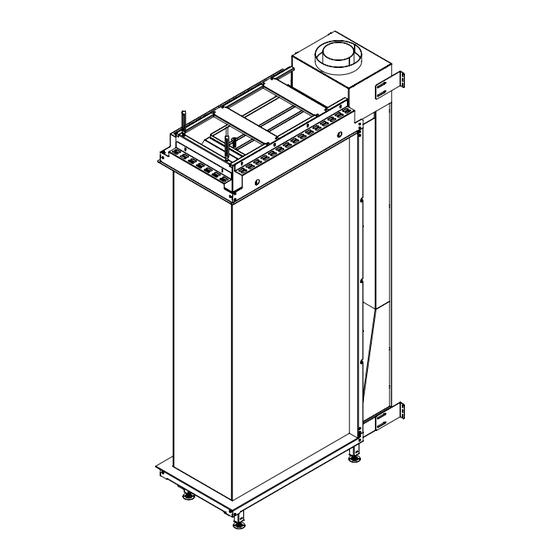
Page 52: D Dimensional Drawings
A P P e n D I C e s D DIMensIonAL DRAWInGs DWG files for design specific dimensions not listed are available On this page and the following ones you will find dimensional www.element4fires.com drawings of the Sky RD series with some of the important for download at dimensions that you have to take into account when installing and installing your fireplace. - Page 53 A P P e n D I C e s Figure D.B - Technical drawing of Sky MRD...
- Page 54 A P P e n D I C e s Figure D.C - Technical drawing of Sky SRD...
-
Page 55: E Spare Parts
A P P e n D I C e s e sPARe PARts Many different parts can be distinguished for the Sky RD models. In this appendix an overview is given of several parts in the fireplace chassis, frame and accessories. Table D.A Please refer to article description in in your... - Page 56 A P P e n D I C e s A P P e n D I C e s Figure E.A - Sky Spare parts Figure E.B - Sky Spare parts 2...
-
Page 57: F Element4 Warranty
Check with your dealer in advance for any costs to you when If a defect exists, Element4 will, at its option, either (1) provide arranging a warranty call. Shipping and/or delivery charges for needed components using new or refurbished replacement parts are not covered by this warranty. - Page 58 A P P e n D I C e s...
- Page 59 A P P e n D I C e s...
- Page 60 Manufactured by: E L E M E N T 4 B .V. Simon Stevinweg 6A 8013 NB Zwolle The Netherlands Info@element4.nl www.element4.nl/en R e L e A s e DAt e | 0 4 / 0 1 / 2 4...
Need help?
Do you have a question about the Sky LR and is the answer not in the manual?
Questions and answers