
Subscribe to Our Youtube Channel
Related Manuals for Sungrow SG30KU


Summary of Contents for Sungrow SG30KU
- Page 1 User Manual SG30KU/SG36KU PV Grid-Connected Inverter SG30KU_SG36KU-UEN-Ver10-201403 Version: 1.0...
- Page 3 About This Manual This manual is for the inverters SG30KU and SG36KU. These inverters are grid-connected, transformer-less, robust and of high conversion efficiency. The device will bring you profit from PV power system. The manual contains information about the inverter, which will provide you guidelines to connect the inverter into the PV power system and operate the inverter.
- Page 4 Symbols Explanation Important instructions contained in this manual should be followed during installation, operation and maintenance of the inverter. And they will be highlighted by the following symbols. DANGER indicates a hazard with a high level of risk which, if not avoided, will result in death or serious injury.
- Page 5 Symbols on the Inverter Body This symbol indicates that you should wait at least 5 minutes after disconnecting the inverter from the utility grid and from the PV input before touching any inner live parts. Hot surface! In order to reduce the risk of burns, do not touch the hot surface when the device is running.
-
Page 6: Table Of Contents
Contents Safety Instructions ..............1 IMPORTANT SAFETY INSTRUCTIONS .............. 1 Arc Fault Detection (AFD) ................... 5 Product Introduction ............... 6 Intended Usage ...................... 6 Product Description ....................7 2.2.1 Product Appearance ....................7 2.2.2 Dimensions of Inverter .................... 8 2.2.3 LCD Display Panel ...................... 8 2.2.4 DC Switch ........................ - Page 7 5.3.3 Installing on the Floor ..................28 5.3.4 Horizontally Installing ..................29 Electrical Connection ............. 31 Connection Conduit Entries ................32 Combiner Unit Description ................33 Connecting Inverter to AC Grid ..............35 6.3.1 AC Side Requirements ..................35 6.3.2 Grid Connection ..................... 35 Connecting Inverter to PV Arrays ..............
- Page 8 9.1.4 Troubleshooting of Faults in LCD Screen ............59 Maintenance ......................64 9.2.1 Routine Maintenance ................... 64 9.2.2 Maintenance Instruction ..................65 Contact Sungrow Service ................68 10 Operation of LCD Display ............69 10.1 Description of Button Function ..............69 10.2...
- Page 9 11 Appendix ................86 11.1 Technical Data ...................... 86 11.2 Grid Over-/Under-voltage Parameter ............88 11.3 Grid Over-/Under-frequency Parameter ............. 88 11.4 P-Q Curve ....................... 88 11.5 Automatic Power Derating ................89 11.5.1 Temperature-related Power Derating ............89 11.5.2 Input Voltage-related Power Derating ............90 11.6 Exclusion of Liability ..................
-
Page 11: Safety Instructions
SG30KU and SG36KU inverter that shall be followed during installation and maintenance of the inverter. The SG30KU and the SG36KU have been designed and tested strictly according to the international safety regulations. As electrical and electronic equipment, safety instructions related to them must be complied with during installation, commissioning, operation and maintenance. - Page 12 1 Safety Instructions User Manual Before Installation There is a risk of injury due to improperly handling the device! Always follow the instructions contained in the manual when moving and positioning the inverter. The weight of the equipment can cause injuries, serious wounds, or bruise if improperly handled.
- Page 13 User Manual 1 Safety Instructions During Inverter Operation Do not open the enclosure when the inverter is under voltage. There is an unlikely but possible risk of explosion in very specific cases of fault. The housing will protect persons and property from such an explosion, only if it is correctly sealed. There is a risk of burn! Prevent from touching device hot parts (such as heat sink) during operation.
- Page 14 1 Safety Instructions User Manual Servicing of the device in accordance with the manual should never be undertaken in the absence of proper tools, test equipment or more recent revision of the manual which is clearly and thoroughly understood. There is a risk of inverter damage if it is improperly serviced. Use only accessories and spare parts approved by the inverter manufacturer.
-
Page 15: Arc Fault Detection (Afd)
The inverter assures to detect the arc fault defined by UL1699B. The DC ARC-Fault circuit is for series arcing faults or a type 1 device. The SG30KU and SG36KU inverter’s DC Arc Fault Detection (AFDI) function is based on the Digital Signal Processor (DSP). -
Page 16: Product Introduction
2 Product Introduction 2.1 Intended Usage SG30KU and SG36KU (They will be referred to as inverter hereinafter unless otherwise specified) which are a 3-phase string inverter without transformer, are crucial unit between the PV strings and utility grid in the PV power system. -
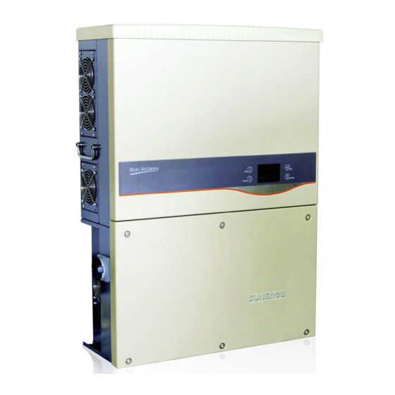
Page 17: Product Description
User Manual 2 Product Introduction 2.2 Product Description 2.2.1 Product Appearance Fig. 2-2 Product Components Description Item Name Description display Inverter operation data viewing parameters panel configuration can be performed via the LCD display panel. Connection Connection openings with plastic threaded plugs for openings connecting conduits. -
Page 18: Dimensions Of Inverter
2 Product Introduction User Manual 2.2.2 Dimensions of Inverter Fig. 2-3 Outline Dimensions of Inverter (unit: mm) 2.2.3 LCD Display Panel As a human-computer interaction interface, LCD display panel comprises LED indicators, buttons and LCD display screen on the front panel of the inverter. LEDs indicate the working status of the inverter The current running information shown on the LCD display Fault records shown on the LCD display... -
Page 19: Dc Switch
User Manual 2 Product Introduction Tab. 2-1 LCD Display Panel Description Name Description “RUN” and “FAULT”. Inverter current state can be known from the indicators two indicators. Detailed definition is shown in Tab. 2-2. Navigate in the LCD menu, set values and so on. Detailed Buttons function is shown in Tab. -
Page 20: Technical Description
RS485 for communication. Inverters are also provided running records display and parameters configuration via human-computer interface – LCD display panel. Fig. 2-5 Main Circuit Diagram of SG30KU and SG36KU *Image shown here is indicative only. Actual product you receive may differ. -
Page 21: Functions Description
User Manual 2 Product Introduction 2.3.2 Functions Description Inverter functions can be grouped as the following: Conversion function Inverter converts the direct current power into alternating current power, which conforms to the grid requirement of its installation country. Data storage and display Inverter stores essential data including running information and fault records, and displays them on integrated LCD display. -
Page 22: Derating
2 Product Introduction User Manual 2.3.3 Derating Derating the output power is a way to protect the inverter from overload and potential faults. Inverter’s derating function can be activated in the following scenarios: PV input overload Grid voltage too low Temperature too high (Inner temperature and power modules temperature) Power limit setting on the inverter LCD display or remote dispatch PV Overload Derating... - Page 23 User Manual 2 Product Introduction When the inner temperature exceeds an upper limit, the inverter start to gradually derating until the temperature decreases to normal range. The deration lower limitation is about 33%. If the modules temperature and the inner temperature are both exceed the limit, the actual derating power value will be the less one.
-
Page 24: Installation Flow
3 Installation Flow Fig. 3-1 shows the installation flow of inverter for installer. Please follow these procedures. Fig. 3-1 Installation Flow Chart... - Page 25 User Manual 3 Installation Flow Tab. 3-1 Description of Installation Flow Order Description Reference Chapter Unpacking and inspection Section 4.1 Read this manual, especially the section on “safety Chapter 1 instruction” Store the inverter unit if not install immediately Section 4.4 Choose the best installation site Section 5.1 Moving the inverter to installation site...
-
Page 26: Unpacking And Storage
4 Unpacking and Storage 4.1 Unpacking and Inspection The unit is thoroughly tested and strictly inspected before delivery. Damage may still occur during shipping. Check the packing for any visible damage upon receiving. Check the inner contents for damage after unpacking. Check the completeness of delivery contents according to the inner packing list. -
Page 27: Available Versions
User Manual 4 Unpacking and Storage 4.2 Available Versions According to their rated output power, the inverters can be divided into 30kW and 36kW. We provide five wiring box versions for equal output power inverters. Tab. 4-1 shows the five wiring box versions. Tab. -
Page 28: Identifying Inverter
Sungrow. Fig. 4-2 Nameplate of Inverters *Image shown here is indicative only. Actual product you receive may differ. -
Page 29: Delivery Contents
User Manual 4 Unpacking and Storage 4.4 Delivery Contents Fig. 4-3 Delivery Contents Item Name Description Inverter unit Backplate It is used for mounting inverter onto the wall. Expansion Seven units. It is used for fastening backplate onto concrete bolts wall. -
Page 30: Storage Of Inverter
During the storage time, periodically check any visible damage by rats and other rodents. Replace the packaging if necessary. The packaging should be kept upright. After long term storage, local installer or service dept. of Sungrow should perform a comprehensive test before connecting the inverter into PV power system. -
Page 31: Mechanical Installation
5 Mechanical Installation 5.1 Selecting Installation Location Selecting an optimal installation location for the inverter is decisive for its operating safety as well as its expected efficiency and service life. Take the load capacity of the wall into account. The wall (such as concrete wall and metal structure) should be strong enough to hold the weight of the inverter over a long period of time. - Page 32 5 Mechanical Installation User Manual The inverter unit with NEMA 4X can be installed indoors or outdoors also. The ambient temperature should range from -25°C to 60°C. The relative humidity of the installation can reach 100%. Moisture may result in corrosion and damage to the internal device components.
-
Page 33: Moving Inverter To Installation Site
User Manual 5 Mechanical Installation Do not install the inverter in a closed cabinet. Otherwise, the inverter will not operate normally. It is necessary to make sure that hot air will be discharged by forced ventilation. Do not install the inverter where children can reach. -
Page 34: Installing The Inverter
5 Mechanical Installation User Manual 5.3 Installing the Inverter Inverter is installed onto the wall by means of backplate enclosed in the packaging. If you don’t use the supplied backplate, you may drill holes refer to its dimension below. Fig. 5-1 Dimensions of Backplate(unit: mm) There are two sets of stainless fasteners supplied for attaching the backplate to concrete wall and metal frame. -
Page 35: Installing On Concrete Wall
User Manual 5 Mechanical Installation 5.3.1 Installing on Concrete Wall Remove backplate and fasteners from the packaging. Step 1 Place the backplate onto the chosen concrete wall and adjust it until it is in a Step 2 horizontal position. Mark the positions to drill holes using the backplate as the template. Step 3 Drill holes according to the marks made before. -
Page 36: Installing On Metal Frame
5 Mechanical Installation User Manual 5.3.2 Installing on Metal Frame Remove backplate and fasteners from the packaging. Step 1 Choose the best installation site according to above requirements. Place the Step 2 backplate onto the chosen metal frame and adjust it until it is in a horizontal position. - Page 37 User Manual 5 Mechanical Installation Item Description Remark Hexagonal socket nut Spring washer Washer Hexagonal bolt M10*45 Metallic wall Backplate Assemble the cap onto the inverter for better weatherproof function. Step 6 Lift up the inverter above the backplate and then slide down to make sure Step 7 that the recesses on the back of the inverter fit perfectly together with the backplate.
-
Page 38: Installing On The Floor
5 Mechanical Installation User Manual 5.3.3 Installing on the Floor Remove floor bracket and fasteners from the packaging. Step 1 Fixing the floor bracket to the inverter. Step 2 Place the floor bracket onto the chosen floor position. Step 3 Mark the positions to drill holes using the floor bracket as the template. -
Page 39: Horizontally Installing
User Manual 5 Mechanical Installation 5.3.4 Horizontally Installing Remove the bracket and fasteners from the packaging. Step 1 Assemble the bracket to the recesses on the back of the inverter and make Step 2 sure them fit perfectly together with the mounting ear. Fix the bracket with two M4×16 screws. - Page 40 5 Mechanical Installation User Manual L1*: Distance from the center of the fans to the floor. L2*: The shortest distance from the top cover of the inverter to the PV panel. You may order the brackets from Sungrow.
-
Page 41: Electrical Connection
6 Electrical Connection Once the inverter is firmly attached to the appropriate location, it can be connected to the PV power system. Installation shall comply with local regulations and technical rules. Improper operation during the wiring process can cause fatal injury to the operator or unrecoverable damage to the inverter. -
Page 42: Connection Conduit Entries
6 Electrical Connection User Manual 6.1 Connection Conduit Entries Conduit entries for all versions are located on the bottom and at the sides of the combiner unit. Conduit entries are illustrated below. Fig. 6-1 Conduit entries Description DC cable openings with plastic threaded plug. Trade size 1-1/2'' AC cable openings with plastic threaded plug. -
Page 43: Combiner Unit Description
User Manual 6 Electrical Connection 6.2 Combiner Unit Description There are five models of the combiner unit available for either the 30 kW or 36 kW versions. The major differences between the five combiner unit layouts are shown below. Tab. 6-1 Complete list of combiner unit components Description Description DC switch... - Page 44 6 Electrical Connection User Manual SG30_36KU-S11-VERSION SG30_36KU-S12-VERSION SG30_36KU-S13-VERSION...
-
Page 45: Connecting Inverter To Ac Grid
User Manual 6 Electrical Connection 6.3 Connecting Inverter to AC Grid 6.3.1 AC Side Requirements Only after receiving prior approval from the local grid company as required, should you connect the inverter to the grid. Prior to connecting to the utility grid, verify whether the grid voltage and frequency are within the range of inverter output parameters, referred to “Appendix”. - Page 46 6 Electrical Connection User Manual The cross-section of the AC cable conductor must be sized in order to prevent accidentally disconnections of the inverter from the grid due to high impedance of the cable that connects the inverter to the power supply point. The table shows the maximum length of the cable conductor based on the cross-section.
- Page 47 User Manual 6 Electrical Connection For conductors with finer stranding, a suitable UL listed wire ferrule must be used. Pull AC cables through the conduit opening and connect the necessary Step 5 conductors to AC pressure type terminal blocks For Wye grid, connect Neutral, L1, L2, L3, and PE conductors. For Delta grid, connect L1, L2, L3, and the PE conductors to the corresponding terminals on the AC Terminal Block.
-
Page 48: Connecting Inverter To Pv Arrays
6 Electrical Connection User Manual 6.4 Connecting Inverter to PV Arrays Lethal voltage exists! PV arrays produce electrical energy when exposed to light and thus can create an electrical shock hazard. Cover the PV arrays with opaque materials and then perform the wiring. Wiring should only be performed by qualified personnel. -
Page 49: Pv Inputs Configuration
User Manual 6 Electrical Connection 6.4.1 PV Inputs Configuration The inverter has two PV input areas DC1 input and DC2 input, each owning its MPP tracker. The two PV inputs can be configured in independent mode or parallel mode. PV Configuration Mode- Independent Mode For independent mode, the two PV inputs work independently, each with its own MPPT. - Page 50 6 Electrical Connection User Manual PV Configuration Mode-Parallel Mode For parallel mode, the PV inputs can be configured in parallel inside the combiner unit. All PV strings connected to the inverter have a homogenous structure, including the same type, the same number, identical tilt and identical orientation. As shown in the following diagram, the inverter may choose parallel mode due to no difference between the two PV inputs.
-
Page 51: Pv Connection Procedures
User Manual 6 Electrical Connection 6.4.2 PV Connection Procedures Conduit entries for all versions are located on the bottom and both side of the combiner unit Make sure the appropriate conduit hub is used in order to maintain required spacing between wiring groups and ensure the integrity of the NEMA 4X environmental rating. - Page 52 6 Electrical Connection User Manual Disconnect the DC switch and locked out. Step 3 Configure PV configuration mode via jumper cables according to actual PV Step 4 conditions. Please refer to”6.4.1 PV Inputs Configuration”. If inverter selects parallel PV configuration mode, you should connect DC1+ to DC2+ and DC1- to DC2- on the DC connection circuit board with jumper cables of cross-section not less than 6mm (10 AWG) as the following diagram shown.
-
Page 53: Grounding The Inverter
User Manual 6 Electrical Connection 6.5 Grounding the Inverter Because of the transformer-less design of the inverter, neither the DC positive pole nor the DC negative pole of the PV string is permitted to be grounded. 6.5.1 Grounding System Overview All non-current carrying exposed metal parts of the equipment and other enclosures in the PV power system should be grounded (e.g., PV arrays frame and inverter enclosure). -
Page 54: Second Protective Earth Terminal
6 Electrical Connection User Manual 6.5.2 Second Protective Earth Terminal The inverter is equipped with second protective earth terminal as specified in EN 50178. Second PE Terminals There are two second PE terminals on the right side of the inverter. Users may choose one to connect PE connection. -
Page 55: Communication Connection
User Manual 6 Electrical Connection 6.6 Communication Connection 6.6.1 Communication Overview The inverter operation information can be transferred via its integrated RS485 interface to a PC with monitoring software (such as SolarInfo Insight), or to data logging device (such as SolarInfo Logger). RS485 is the standard communication choice for inverter. -
Page 56: Communication System
6 Electrical Connection User Manual 6.6.2 Communication System For Single Inverter Where there is only one inverter, a RS485 cable enables connection between inverter and data logging device. Communication Connection Terminating (RS 485 A/B bus or RJ 45) Inverter Resistor RS 485 A/B bus RJ 45 Only out. - Page 57 User Manual 6 Electrical Connection Communication Connection Terminating (RS 485 A/B bus or RJ 45) Inverter Resistor RS 485 A/B bus RJ 45 Only out Only out Inverter 1 In and Out In and Out Inverter 2…n-1 In and Out In and Out Inverter n...
-
Page 58: Rs485 Communication Connection
If there is more than one inverter to communicate with a PC or a data logger, it is crucial to configure the communication parameters of each inverter. See “10.12 Communication Parameters Setting”. SolarInfo logger and RS485-232 converter are optional parts and can be ordered from Sungrow. - Page 59 6) to data logging device or RS485-232 converter. Communication terminal definition is referred to the device manual. Verify communication connection configure Step 10 communication parameters. SolarInfo logger and RS485-232 converter are optional parts and can be ordered from Sungrow.
-
Page 60: Configurable Dry Contact
6.6.5 RS485-NET Converting Card (Optional) You may plug a RS485-NET converting card in CON10 and fix it on the Communication Circuit Board with the delivery screws. The RS485-NET converting card is an optional part and can be ordered from Sungrow. -
Page 61: Commissioning
Step 2 Suppose there are sufficient sunlight and enough DC power. PV arrays initialize and supply DC power to inverter. The LCD display is activated to check the validity first. If there is a defect on the display, contact Sungrow. - Page 62 7 Commissioning User Manual Press to choose country code. Confirm Step 3 the settings by Pressing ENTER Select the country code according to the Step 4 inverter’s installation country. Each country code represents corresponding local protective parameters that have been preset before delivery.
- Page 63 User Manual 7 Commissioning After configuring the Grid Code, there will Step 7 be a “Pro-param” type selection screen and then corresponding sub-menu will come up. For detailed information, please refer to “10.11 Protective Parameters Setting”. Configure time according to the local time. Step 8 Time setting is very important, which directly affects data logging.
-
Page 64: Disconnecting, Dismantling And Disposing The Inverter
8 Disconnecting, Dismantling and Disposing the Inverter 8.1 Disconnecting the Inverter For maintenance work or any service work, inverter must be switched off. In normal operation, switching off is not necessary. In order to disconnect the inverter from the AC and DC power sources, you should proceed with the following procedures. -
Page 65: Dismantling The Inverter
User Manual 8 Disconnecting, Dismantling and Disposing the Inverter 8.2 Dismantling the Inverter Remove the cap and loose the screws from the upper lid. Lift up the upper lid slightly, release the locking part of the ribbing of the LED screen and remove the lid. - Page 66 8 Disconnecting, Dismantling and Disposing the Inverter User Manual Unscrew all connection screws between the electrical cabinet and the combiner box with a suitable spanner and detach the electrical cabinet from the combiner box.
-
Page 67: Disposing The Inverter
User Manual 8 Disconnecting, Dismantling and Disposing the Inverter 8.3 Disposing the Inverter Users should take the responsibility for the disposal of the inverter. Some parts and devices in the inverter, such as LCD displayer, batteries, capacitors, may cause environment pollution. Users must comply with the related local regulations to avoid causing pollution. -
Page 68: Troubleshooting And Maintenance
2. Perform troubleshooting in according to fault type in LCD “Fault” indicator is lit screen. See “9.1.4 Troubleshooting of Faults in LCD Screen”. 3. If it cannot be solved, please contact Sungrow. “RUN” indicator Warning fault occurs of the inverter. -
Page 69: Arc Fault Detection Self-Test Fault
3. If the grid voltage is within the permissible range, contact Sungrow Service Dept.. Inverter checked 1. This is a short-term fault due to grid that the instantaneous condition. Wait a moment for inverter... - Page 70 3. Check whether AC fuses are blown out. 4. Check whether grid is not on service. 5. If all conditions are OK and this fault still occurs in the LCD screen, contact Sungrow Service Dept.. The DC component of 1. Wait a moment for inverter recovery.
- Page 71 Fault Description Troubleshooting Code solution. 3. If the grid frequency is within the permissible range, contact Sungrow Service Dept.. The average grid voltage 1. Wait a moment for inverter recovery. over 10 minutes is not 0014 2. If the fault occurs repeatedly, contact within the permissible Sungrow Service Dept..
- Page 72 1. Wait a moment for inverter recovery. There is a fault with 0041 2. If the fault occurs repeatedly, contact sampling channel. Sungrow Service Dept.. If the fault occurs repeatedly, contact Sungrow 0042 Current imbalance. Service Dept.. Disconnect inverter to stop. Wait for ambient ambient temperature to rise above -25 ℃...
- Page 73 0071 Fault with AC SPD It is necessary to replace the SPD module. 0072 Fault with DC SPD Contact Sungrow Service Dept.. Disconnect inverter and replace the fuses. 0073 Fuse has blown out Contact Sungrow Service Dept.. fault occurred...
-
Page 74: Maintenance
PV strings. 532-547 of PVS connection. 2. If the fault still exists, please contact with SUNGROW. 1. Check whether the PV array is shielded. If the PV array is clear and is not shielded, check whether the PV modules are faulty. -
Page 75: Maintenance Instruction
Check the fuses and the DC SPD. Devices Replace the fuse. Every 6 months check Contact Sungrow to order new DC SPDs. Check the LCD stop and emergency stop circuit of the system. Safety Simulate shutdown and check stop signal... - Page 76 9 Troubleshooting and Maintenance User Manual Loosen the screws as the right diagram shown. Disassemble the metal plate slightly. Release the locking part of four connectors by pressing on the ribbing of the locking hooks and pull outwards. Remove fans from the inverter. You can clean the dirty fans with soft brush or vacuum cleaner.
- Page 77 Check, using a multimeter, the assignment and conductivity of the fuse. A fault occurs to the related fuse if it is non-conductive. Check the fault fuse by installer. New fuse can be ordered from Sungrow. Remove the fuse puller by pulling the handle and replace the blown out fuse.
-
Page 78: Contact Sungrow Service
9 Troubleshooting and Maintenance User Manual 9.3 Contact Sungrow Service Should you have any problems in operating on the inverter, please contact us: Service hotline: +86 551 65327817 Email: service@sungrow.cn We need the following information to provide you the best assistance:... -
Page 79: Operation Of Lcd Display
10 Operation of LCD Display 10.1 Description of Button Function Inverter offers two buttons for user to look up the running information and configure parameters. The two buttons have multiple functions. Please refer to Tab. 10-1 before any operation onto inverter. Tab. -
Page 80: Inverter Menu Structure
10 Operation of LCD Display User Manual 10.2 Inverter Menu Structure Fig. 10-1 Menu Tree-English... -
Page 81: Main Screen
User Manual 10 Operation of LCD Display 10.3 Main Screen If the inverter succeeds in commissioning, LCD display will enter into the main screen, as shown in Fig. 10-2. Fig. 10-2 Main Screen Description Description Power curve. x-axis: time in hours; y-axis: output power yield Pin %. Icons (refer to the Tab. -
Page 82: Adjust Contrast
10 Operation of LCD Display User Manual Dispatch LCD power limitation or remote dispatch. Derating Input overload or over-temperature. Communication between device internal control modules and HMI Com-err modules failure. If inverter is in “Fault” state, Press to view multiple “Current fault” information pages. -
Page 83: Detailed Running Information
User Manual 10 Operation of LCD Display 10.5 Detailed Running Information On the main screen, there is some basic information about the inverter. For more detailed running information, please operate as follows. Main Screen(Press ENTER)→Menu→Run-info(Press ENTER) LCD screen will show four detailed running information pages. Scroll pages by pressing “DC power input”... -
Page 84: History Records
10 Operation of LCD Display User Manual 10.6 History Records 10.6.1 Running Information Records )→His-record(Press ENTER) Main Screen(Press ENTER)→Menu(Press →Run-record(Press ENTER) “Run-record” display, press to select the date you want to view. Confirm pressing ENTER. Inverter shows historical running information pages. -
Page 85: Start And Stop Inverter
User Manual 10 Operation of LCD Display 10.7 Start and Stop Inverter → → ×2) Main Screen(Press ENTER) Menu(Press Start/Stop(Press ENTER) Press to choose “Start”/”Stop” and press ENTER to confirm the choice. Press ENTER to confirm. 10.8 Input Parameter Settings Password The parameter settings are protected by the password. -
Page 86: System Parameters Setting
10 Operation of LCD Display User Manual Press to confirm the password and .enter ENTER the “Set-param” sub menu. 10.9 System Parameters Setting 10.9.1 Time Setting If there is deviation between the time on inverter main screen and your local time, you should perform the operation time setting. -
Page 87: Load Default
User Manual 10 Operation of LCD Display 10.9.3 Load Default All history information will be unrecoverable cleared and all parameters will return to the default value except the protection parameters and time once the “load default” operation is performed. ×3)→Set-param(Press ENTER) Main Screen(Press ENTER)→Menu screen(Press →Enter password(Press ENTER)→Sys-param(Press ENTER, Press ×3)→Load... -
Page 88: Running Parameters Setting
10 Operation of LCD Display User Manual 10.10 Running Parameters Setting 10.10.1 Main Menu of Run-param ×3)→Set-param(Press Main Screen(Press ENTER )→Menu screen(Press ENTER)→Enter password(Press ENTER, Press )→Run-param(Press ENTER) On the “Run-param” screen, Press to move arrow to one item and Press ENTER to start this item setting. -
Page 89: Reactive Power Regulation
User Manual 10 Operation of LCD Display 10.10.2 Reactive Power Regulation The inverter provides reactive power regulation function. Use the “ ” Q-Var switch parameter to activate this function and select proper regulation mode. Mode Explanation The reactive power can be regulated by the parameter PF (Power Factor). The reactive power can be regulated by the parameter Q-Var limits (in %). -
Page 90: Protective Parameters Setting
A password confirmation screen will occur. Press move cursor right and Press to input the password. Please ask Sungrow or your dealer for this password. To make protective parameters setting convenient, inverter provides country code selection. The protective parameters have been configured before delivery... - Page 91 User Manual 10 Operation of LCD Display Press to select protective parameter type. Press ENTER to confirm the selection. Single-stage Protective Parameter selected protective parameter type “Single-stage”, the following sub-menu will come up. Press to select parameter, Press to move cursor right and Press to set the appropriate value.
- Page 92 10 Operation of LCD Display User Manual Tab. 10-6 Multi-stage Protective Parameter Explanation Parameter Explanation Max-V. prot Over-voltage protection Ⅰ-Max-V. grid Stage Ⅰ Grid over-voltage (U>) Ⅰ-Max-V. time Stage Ⅰ Grid over-voltage (U>) tripping time Ⅱ-Max-V. grid Stage Ⅱ Grid over-voltage (U>>) Ⅱ-Max-V.
-
Page 93: Communication Parameters Setting
User Manual 10 Operation of LCD Display 10.12 Communication Parameters Setting ×3)→Set-param(Press ENTER) Main Screen(Press ENTER )→Menu screen(Press →Enter password(Press ENTER, Press ×3)→Com-param(Press ENTER) Press to move cursor right and Press to set the appropriate value. Confirm settings by Pressing ENTER. -
Page 94: Afd Settings
10 Operation of LCD Display User Manual When the PV inputs are changed, the corresponding “fault” state will be shown on the main screen. You can perform the PVS Detect Reset function to re-detect the PV input strings number. 10.13.2 AFD Settings ×4)→Advanced Settings(Press Main Screen(Press ENTER... - Page 95 User Manual 10 Operation of LCD Display If a potential problem on the AFD board is detected, the self-test will result in fault.
-
Page 96: Appendix
11 Appendix 11.1 Technical Data Parameters SG30KU SG36KU Input Side Data Max. PV input power 34100W 41000W Max. input voltage 1000Vdc Startup voltage 300V Nominal input voltage 710V MPP voltage range 280...950Vdc MPP voltage range for nominal power 480...850Vdc 560...850Vdc No. - Page 97 Parameters SG30KU SG36KU DC fuse Integrated Type III surge arrester Overvoltage protection (Optional Type II DIN rail surge arrester) AC switch Optional AC fuse Optional System data Max. efficiency 98.5% CEC efficiency 98.0% Isolation method Transformerless Ingress protection rating NEMA4X Night power consumption <1W...
-
Page 98: Grid Over-/Under-Voltage Parameter
11.2 Grid Over-/Under-voltage Parameter Voltage(at PCC) Trip time(s) 0.16 V<50% Adjustable 0.16 to 2 50%≤V<88%(adjustable) Normal operation 88%≤V≤110%(adjustable) Adjustable 0.16 to 1 110%<V<120% 0.16 V>120% 11.3 Grid Over-/Under-frequency Parameter Frequency range(Hz) Clearing time(s) >60.5 0.16 < {59.8-57.0} Adjustable 0.16 to 300 (adjustable set point) <57.0 0.16... -
Page 99: Automatic Power Derating
11.5 Automatic Power Derating In order to maintain safe inverter operation under adverse environmental conditions or due to improper input voltages, the unit automatically reduces the amount of power it feeds to the grid. 11.5.1 Temperature-related Power Derating Operating parameters, such as input voltage, grid voltage and power available from the photovoltaic arrays can affect the power derating caused by ambient or inverter temperature. -
Page 100: Input Voltage-Related Power Derating
11.5.2 Input Voltage-related Power Derating The following graph shows the automatic reduction in output power when the input voltage exceeds the threshold value. -
Page 101: Exclusion Of Liability
Damages caused by irresistible natural environment The use of supplied software produced by Sungrow Power Supply Co., Ltd. is subject to the following conditions: Sungrow Power Supply Co., Ltd. rejects any liability for direct or indirect damages arising from the use of the SolarInfo software. -
Page 102: About Us
The power rating of Sungrow products covers from hundred watt to mega-watt systems. The vision of Sungrow is to help our customers acquire stable and clean power with minimum cost, maximum reliability and enhanced safety.
Need help?
Do you have a question about the SG30KU and is the answer not in the manual?
Questions and answers