
Related Manuals for SIGMATEK CO 041


Summary of Contents for SIGMATEK CO 041
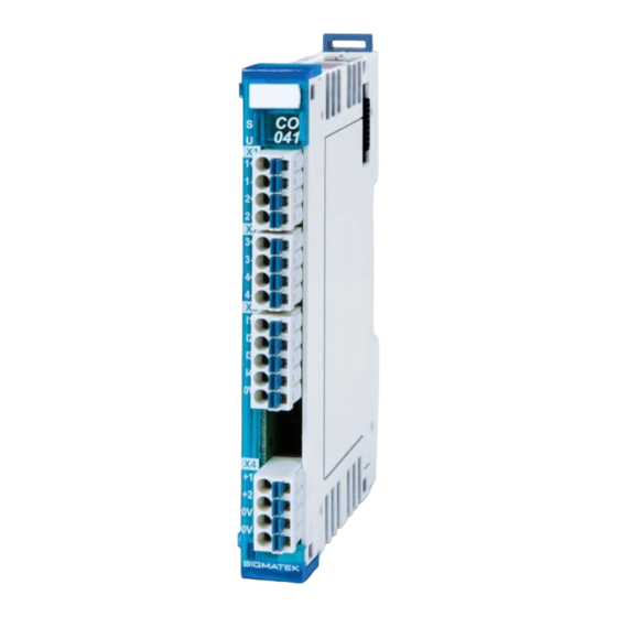
- Page 1 CO 041 S-DIAS Current Output Module Instruction Manual Date of creation: 29.05.2018 Version date: 26.07.2023 Article number: 20-030-041-E...
- Page 2 (print, photocopy, microfilm or in any other process) without the express permission. We reserve the right to make changes in the content without notice. The SIGMATEK GmbH & Co KG is not responsible for technical or printing errors in the handbook and assumes no responsibility for damages that occur...
- Page 3 4 current controlled outputs /pulse outputs 4 digital inputs +5 V The S-DIAS CO 041 current output module is used for the simultaneous operation of four valves on supply voltages from 18-55 volts, a maximum holding current of 1 A and maximum output current of 3.5 A.
-
Page 4: Table Of Contents
CO 041 S-DIAS CURRENT OUTPUT MODULE Contents Introduction ................5 Target Group/Purpose of this Operating Manual ...... 5 Important Reference Documentation ......... 5 Contents of Delivery ..............5 Basic Safety Directives ............6 Symbols Used ................6 Disclaimer ..................8 General Safety Directives ............ - Page 5 S-DIAS CURRENT OUTPUT MODULE CO 041 Mechanical Dimensions ............21 Connector Layout ..............22 Status LEDs ................. 23 Applicable Connectors ............... 23 Labeling Field ................24 Output Scheme ................25 7.4.1 Use as a Current Controlled PWM Output for Direct Valve Control .. 25 7.4.2...
- Page 6 CO 041 S-DIAS CURRENT OUTPUT MODULE 14 Addressing ................33 15 Hardware Class CO041 ............37 15.1 General ..................38 15.2 Current - PWM Outputs 1-4 ............40 15.3 Digital Inputs 1-4 ................. 40 15.4 Communication Interfaces ............40 15.5 Global Methods ................41 15.5.1...
-
Page 7: Introduction
General knowledge of automation technology is required. Further help and training information, as well as the appropriate accessories can be found on our website www.sigmatek-automation.com. Our support team is happily available to answer your questions. Please see our website for our hotline number and business hours. -
Page 8: Basic Safety Directives
CO 041 S-DIAS CURRENT OUTPUT MODULE Basic Safety Directives Symbols Used The following symbols are used in the operator documentation for warning and danger messages, as well as informational notes: DANGER Danger indicates that death or serious injury will occur, if the specified measures are not taken. - Page 9 S-DIAS CURRENT OUTPUT MODULE CO 041 INFORMATION Information Provides important information on the product, handling or relevant sections of the documentation, which require attention. 26.07.2023 Page 7...
-
Page 10: Disclaimer
It does not guarantee properties under the warranty. Please thoroughly read the corresponding documents and this operating manual before handling a product. SIGMATEK GmbH & Co KG is not liable for damages caused through, non-compliance with these instructions or applicable regulations. -
Page 11: General Safety Directives
S-DIAS CURRENT OUTPUT MODULE CO 041 General Safety Directives The Safety Directives in the other sections of this operating manual must be observed. These instructions are visually emphasized by symbols. INFORMATION According to EU Directives, the operating manual is a component of a product. -
Page 12: Software/Training
CO 041 S-DIAS CURRENT OUTPUT MODULE CAUTION Handle the device with care and do not drop or let fall. Prevent foreign bodies and fluids from entering the device. The device must not be opened! Manipulez l’appareil avec précaution et ne le laissez pas tomber. -
Page 13: Standards And Directives
The product was constructed in compliance with the following European Union directives and tested for conformity. 3.1.1 EU Conformity Declaration EU Declaration of Conformity The product CO 041 conforms to the following European directives: • 2014/35/EU Low-voltage Directive • 2014/30/EU Electromagnetic Compatibility (EMC Directive) •... -
Page 14: Type Plate
CO 041 S-DIAS CURRENT OUTPUT MODULE 4 Type Plate HW: Hardware version SW: Software version Page 12 26.07.2023... -
Page 15: Technical Data
S-DIAS CURRENT OUTPUT MODULE CO 041 Technical Data Current Controlled PWM Outputs Number Configuration plus-switching (current controlled) Short-circuit proof Maximum inrush current/channel 3.5 A (corresponds to setpoint inrush current 100 %) Minimum inrush current/channel 0,30 A (corresponds to setpoint inrush current 8.5 %) Maximum holding current/channel 1.35 A... - Page 16 CO 041 S-DIAS CURRENT OUTPUT MODULE Current controlled PWM output – schematic Page 14 26.07.2023...
-
Page 17: Pulse Signal Output Specifications
S-DIAS CURRENT OUTPUT MODULE CO 041 Pulse Signal Output Specifications Number Configuration Push-Pull (voltage controlled) Short-circuit proof Maximum holding current/channel 1.0 A Maximum total current per supply 2.0 A group (+UV1/+UV2) Min. Activation time 50 µs Turn-on delay Adjustable via software in 1 µs increments from 0-32767 Turn-off delay Adjustable via software in 1 µs increments from 0-32767... - Page 18 CO 041 S-DIAS CURRENT OUTPUT MODULE Pulse signal output – schematic Page 16 26.07.2023...
-
Page 19: Digital Input Specifications
4x LED (green) Stand-Alone Operating Mode For operation in stand-alone mode, the module must be connected to a SIGMATEK CPU and configured using a hardware class. Via the configuration, all values for inrush current, holding current and the holding current period for stand-alone mode are remnantly stored in the module. -
Page 20: Electrical Requirements
CO 041 S-DIAS CURRENT OUTPUT MODULE Electrical Requirements Valve supply voltages +UV/1-2 18-55 V Current consumption of the corresponds to the load on valve outputs valve supply +UV/1-2 Voltage supply from S-DIAS +24 V Current consumption on the S- typically 35 mA... - Page 21 S-DIAS CURRENT OUTPUT MODULE CO 041 26.07.2023 Page 19...
-
Page 22: Miscellaneous
CO 041 S-DIAS CURRENT OUTPUT MODULE Miscellaneous Article number 20-030-041 Standard Environmental Conditions Storage temperature -20 ... +85 °C ambient temperature 0 ... +55 °C Humidity 0-95 %, non-condensing Installation altitude above sea 0-2000 m without derating level > 2000 m up to a maximum of 5000 m with derating of the maximum environmental temperature by 0.5 °C per 100 m... -
Page 23: Mechanical Dimensions
S-DIAS CURRENT OUTPUT MODULE CO 041 Mechanical Dimensions 26.07.2023 Page 21... -
Page 24: Connector Layout
CO 041 S-DIAS CURRENT OUTPUT MODULE Connector Layout INFORMATION The GND supply (X4: Pin 3 and Pin 4) is internally bridged. Only one GND pin (pin 3 or pin 4) is required to power the module. The bridged connections may be used for further looping of the GND supply. -
Page 25: Status Leds
S-DIAS CURRENT OUTPUT MODULE CO 041 Status LEDs Module status green module active no supply available BLINKING (5 Hz) No communication / stand-alone mode User yellow can be set from the application (e.g. the module LED can be set to blinking through the... -
Page 26: Labeling Field
CO 041 S-DIAS CURRENT OUTPUT MODULE Labeling Field Manufacturer Weidmüller Type MF 10/5 CABUR MC NE WS Article number Weidmüller 1854510000 Compatible printer Weidmüller Type Printjet Advanced 230V Article number Weidmüller 1324380000 Page 24 26.07.2023... -
Page 27: Output Scheme
S-DIAS CURRENT OUTPUT MODULE CO 041 Output Scheme 7.4.1 Use as a Current Controlled PWM Output for Direct Valve Control 7.4.2 Use as an Pulse Signal Output for Controlling Valve Control Electronics 26.07.2023 Page 25... -
Page 28: Wiring
CO 041 S-DIAS CURRENT OUTPUT MODULE Wiring Wiring Example Page 26 26.07.2023... -
Page 29: Notes
S-DIAS CURRENT OUTPUT MODULE CO 041 Notes The following guidelines should be observed: • The DIN rail must have an adequate mass connection. • The shielding must be connected to a shielding bus. • Avoid parallel connections between input lines and load-bearing circuits. -
Page 30: Assembly/Installation
CO 041 S-DIAS CURRENT OUTPUT MODULE Assembly/Installation Check Contents of Delivery Ensure that the contents of the delivery are complete and intact. See chapter 1.3 Contents of Delivery. INFORMATION On receipt and before initial use, check the device for damage. If the device is damaged, contact our customer service and do not install the device in your system. -
Page 31: Mounting
S-DIAS CURRENT OUTPUT MODULE CO 041 Mounting The S-DIAS modules are designed for installation into the control cabinet. To mount the modules, a DIN-rail is required. The DIN rail must establish a conductive connection with the back wall of the control cabinet. The individual S-DIAS modules are mounted on the DIN rail as a block and secured with latches. - Page 32 CO 041 S-DIAS CURRENT OUTPUT MODULE Recommended minimum distances of the S-DIAS modules to the surrounding components or control cabinet wall: a, b, c … distances in mm (inches) ϑ … valid ambient temperature in °C (°F) Page 30 26.07.2023...
-
Page 33: Transport/Storage
S-DIAS CURRENT OUTPUT MODULE CO 041 10 Transport/Storage INFORMATION This device contains sensitive electronics. During transport and storage, high mechanical stress must therefore be avoided. For storage and transport, the same values for humidity and vibration as for operation must be maintained! Temperature and humidity fluctuations may occur during transport. -
Page 34: Maintenance
CO 041 S-DIAS CURRENT OUTPUT MODULE 12 Maintenance INFORMATION During maintenance as well as servicing, observe the safety instructions from chapter 2 Basic Safety Directives. 12.1 Service This product was constructed for low-maintenance operation. 12.2 Repair INFORMATION In the event of a defect/repair, send the device with a detailed error description to the address listed at the beginning of this document. -
Page 35: Addressing
S-DIAS CURRENT OUTPUT MODULE CO 041 14 Addressing Address Size Access Description Reset Value (hex) (bytes) Type Write PDO (up to 32 bytes) Programmable output 1 Step Frequency Register 0000 r/w32 Frequency of one step in 64-micro steps 00000000 (Internal signal is 21Bit) Start-time 1 Bit 14..0: Start-time... - Page 36 CO 041 S-DIAS CURRENT OUTPUT MODULE 001C r16/w16 Start-time 2 0000 001E r16/w16 Stop-time 2 0000 0020 Reserved 0..0 SDO1 Data with 26 Bytes Programmable output 1 0030 Flash Stop-time period [µs] (min. 2) Programmable output 2 0032 Flash Stop-time period [µs] (min. 2)
- Page 37 S-DIAS CURRENT OUTPUT MODULE CO 041 MicroBlaze Debugging and Scratch Pad 00E0 0..0 (NO write access) 00F0 Reserved 0..0 MicroBlaze Status Register Bit 0: calibration data could not be read Bit 1: Calibration data CRC invalid Bit 2: Reserved 00FF...
- Page 38 CO 041 S-DIAS CURRENT OUTPUT MODULE Current threshold register Bit 0: Valve 1 upper threshold reached Bit 1: Valve 2 upper threshold reached Bit 2: Valve 3 upper threshold reached 0106 Bit 3: Valve 4 upper threshold reached Bit 4: Valve 1 lower threshold reached...
-
Page 39: Hardware Class Co041
15 Hardware Class CO041 Hardware Class CO041 for the S-DIAS current output module CO 041 This hardware class is used to control the CO 041 hardware module. The module has 4 current- or pulse outputs with adjustable starting and lowering current. -
Page 40: General
CO 041 S-DIAS CURRENT OUTPUT MODULE 15.1 General ClassState State This server shows the actual status of the hardware class. DeviceID State This server shows the device ID of the hardware module. FPGAVersion State FPGA version of the module in the format 16#XY (e.g. - Page 41 S-DIAS CURRENT OUTPUT MODULE CO 041 Extern Voltage State This server indicates whether the external module supply is OK for the respective output. Bit 0 Output 1-2 Bit 1 Output 3-4 Range State This server indicates whether a short-circuit has occurred on a valve. More...
-
Page 42: Current - Pwm Outputs 1-4
CO 041 S-DIAS CURRENT OUTPUT MODULE 15.2 Current - PWM Outputs 1-4 Config Valid State Indicates whether the configuration of the current outputs is valid. configuration currently being written configuration valid error Calibdata State State Indicates whether an error has occurred when reading the calibration data of the current outputs. -
Page 43: Global Methods
S-DIAS CURRENT OUTPUT MODULE CO 041 15.5 Global Methods The following methods can be called via the ClassState server. 15.5.1 SetStartTime With this function, the preset times until the next pulse to be started is switched off can be set for each output of the module. Two different, independent start times can be assigned. -
Page 44: Setstoptime
CO 041 S-DIAS CURRENT OUTPUT MODULE 15.5.2 SetStopTime With this function, the preset times until the current or the next pulse is switched off can be set for each output of the module. Two different, independent stop times can be assigned. -
Page 45: Internal Properties
S-DIAS CURRENT OUTPUT MODULE CO 041 15.6 Internal Properties 15.6.1 Stand-alone Operation To use stand-alone operation, valid configuration data must be stored in the module during initial commissioning. The new configuration data can be saved in the SPI Flash using the "SafeConfig"... -
Page 46: Timing On The Local S-Dias
CO 041 S-DIAS CURRENT OUTPUT MODULE 15.6.3 Timing on the local S-DIAS The outputs are always started after SyncOut. The SyncOut is shifted by 25 µs to the SDIAS ISO start time. This must be taken into account when selecting the start or stop time. -
Page 47: S-Dias Timing Behind Varan
S-DIAS CURRENT OUTPUT MODULE CO 041 15.6.4 S-DIAS timing behind VARAN When using a VI, the SDIAS Sync is the same as the CPU Sync. The SyncOut is shifted by 25 µs to the SDIAS Sync. This must be taken into account when selecting the start or stop time. - Page 48 CO 041 S-DIAS CURRENT OUTPUT MODULE Documentation Changes Change date Affected page(s) Chapter Note 18.06.2018 1.1 Current table and footnotes extended Controlled PWM Outputs 20.09.2018 3 Connector Layout Note added 14.11.2019 7 Supported Cycle Chapter added Times 28.02.2020 7 Supported Cycle...
Need help?
Do you have a question about the CO 041 and is the answer not in the manual?
Questions and answers