
Related Manuals for SIGMATEK AI 088-1


Summary of Contents for SIGMATEK AI 088-1
- Page 1 AI 088-1 S-DIAS Analog Input Module Instruction Manual Date of creation: 20.09.2017 Version date: 26.07.2023 Article number: 20-009-088-1E...
- Page 2 (print, photocopy, microfilm or in any other process) without the express permission. We reserve the right to make changes in the content without notice. The SIGMATEK GmbH & Co KG is not responsi- ble for technical or printing errors in the handbook and assumes no responsibility for damages that occur through...
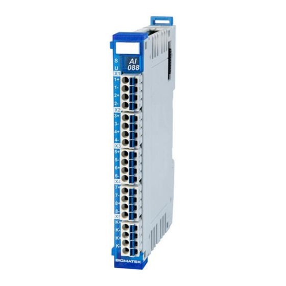
- Page 3 2 KTY temperature sensor inputs 1 KTY11-62 temperature sensor The S-DIAS AI 088-1 analog input module has eight thermal element inputs for all conventional thermal element types. The module also has two inputs for KTY temperature sensors or, starting with hardware version HW3.0, integrated temperature sensors for coupling compen-...
-
Page 4: Table Of Contents
AI 088-1 S-DIAS ANALOG INPUT MODULE Contents Introduction ....................5 Target Group/Purpose of this Operating Manual ...... 5 Important Reference Documentation ......... 5 Contents of Delivery ..............5 Basic Safety Directives ................6 Symbols Used ................6 Disclaimer ..................8 General Safety Directives ............ - Page 5 S-DIAS ANALOG INPUT MODULE AI 088-1 Environmental Conditions ............17 Mechanical Dimensions ................18 Connector Layout ..................19 Status LEDs ................. 20 Applicable Connectors ............... 20 Label Field ................... 21 Wiring ......................22 Wiring Example ................22 Notes .................... 23 8.2.1...
- Page 6 AI 088-1 S-DIAS ANALOG INPUT MODULE Transport/Storage ..................35 Storage ......................35 Maintenance ....................36 14.1 Service ..................36 14.2 Repair ................... 36 Disposal ....................... 36 Hardware Class AI088_1 ................37 16.1 General ..................38 16.2 Analog Inputs 1-8 ................ 39 16.3...
-
Page 7: Introduction
General knowledge of automation technology is required. Further help and training information, as well as the appropriate accessories can be found on our website www.sigmatek-automation.com. Our support team is happily available to answer your questions. Please see our website for our hotline number and business hours. -
Page 8: Basic Safety Directives
AI 088-1 S-DIAS ANALOG INPUT MODULE Basic Safety Directives Symbols Used The following symbols are used in the operator documentation for warning and danger messages, as well as informational notes: DANGER Danger indicates that death or serious injury will occur, if the speci- fied measures are not taken. - Page 9 S-DIAS ANALOG INPUT MODULE AI 088-1 INFORMATION Information Provides important information on the product, handling or relevant sections of the documentation, which require atten- tion. 26.07.2023 Page 7...
-
Page 10: Disclaimer
It does not guarantee properties under the warranty. Please thoroughly read the corresponding documents and this operat- ing manual before handling a product. SIGMATEK GmbH & Co KG is not liable for damages caused through, non-compliance with these instructions or applicable regulations. -
Page 11: General Safety Directives
S-DIAS ANALOG INPUT MODULE AI 088-1 General Safety Directives The Safety Directives in the other sections of this operating manual must be observed. These instructions are visually emphasized by symbols. INFORMATION According to EU Directives, the operating manual is a component of a product. -
Page 12: Software/Training
AI 088-1 S-DIAS ANALOG INPUT MODULE CAUTION Handle the device with care and do not drop or let fall. Prevent foreign bodies and fluids from entering the device. The device must not be opened! Manipulez l’appareil avec précaution et ne le laissez pas tomber. -
Page 13: Standards And Directives
The product was constructed in compliance with the following European Union directives and tested for conformity. 3.1.1 EU Conformity Declaration EU Declaration of Conformity The product AI 088-1 conforms to the following European directives: • 2014/35/EU Low-voltage Directive • 2014/30/EU Electromagnetic Compatibility (EMC Directive) •... -
Page 14: Type Plate
AI 088-1 S-DIAS ANALOG INPUT MODULE Type Plate HW: Hardware version SW: Software version Page 12 26.07.2023... -
Page 15: Technical Data
S-DIAS ANALOG INPUT MODULE AI 088-1 Technical Data Thermal Element Input Specifications Number of channels Measurement range see the following table, Measurement Ranges Thermal elements Converter resolution 16-bit Conversion time per channel 1 ms Common mode range ±10 V Input resistance 2 M... -
Page 16: Measurement Ranges
AI 088-1 S-DIAS ANALOG INPUT MODULE Measurement Ranges 5.2.1 Measurement Ranges Thermal Elements Type Thermocouple Measurement range Measurement Measurement value Error -10 …+850 °C (-0.501-48.715 mV) Fe-CuNi -100-8500 0.0062 %/Ω -40 … +1200 °C (-1.527-48.838 mV) NiCr-Ni -400-12000 0.0061 %/Ω... -
Page 17: Temperature Sensor Input Specifications For Thermocoupling Compensation
S-DIAS ANALOG INPUT MODULE AI 088-1 Temperature Sensor Input Specifications for Thermocoupling Com- pensation Number of channels Sensor type KTY 10-62 or KTY 11-62 Measurement range -20 ... +80 °C Measurement value -200 ... +800 An open or shorted input returns -2147483632 in the hardware class. - Page 18 AI 088-1 S-DIAS ANALOG INPUT MODULE Page 16 26.07.2023...
-
Page 19: Miscellaneous
S-DIAS ANALOG INPUT MODULE AI 088-1 Miscellaneous Article number 20-009-088-1 Standard UL 508 (E247993) Approvals UL, cUL, CE Environmental Conditions Storage temperature -20 ... +85 °C Environmental temperature 0 ... +60 °C Humidity 0-95 %, non-condensing Installation altitude above sea... -
Page 20: Mechanical Dimensions
AI 088-1 S-DIAS ANALOG INPUT MODULE Mechanical Dimensions Page 18 26.07.2023... -
Page 21: Connector Layout
S-DIAS ANALOG INPUT MODULE AI 088-1 Connector Layout The temperature sensors for the coupling compensation (KTY1, KTY2 or starting from HW3.0, internal temperature sensors) can be set individually for any thermo element input. If the KTY temperature input is not needed for coupling compensation, they can also be used as independent temperature sensors. -
Page 22: Status Leds
AI 088-1 S-DIAS ANALOG INPUT MODULE Status LEDs Module Status green module active no supply available BLINKING (5 Hz) no communication User yellow can be set from the application (e.g. the module LED can be set to blinking through the visuali-... -
Page 23: Label Field
S-DIAS ANALOG INPUT MODULE AI 088-1 Label Field Manufacturer Weidmüller Type MF 10/5 CABUR MC NE WS Weidmüller article number 1854510000 Compatible printer Weidmüller Type Printjet Advanced 230V Weidmüller article number 1324380000 26.07.2023 Page 21... -
Page 24: Wiring
AI 088-1 S-DIAS ANALOG INPUT MODULE Wiring Wiring Example Page 22 26.07.2023... -
Page 25: Notes
S-DIAS ANALOG INPUT MODULE AI 088-1 Notes 8.2.1 General Notes The signals recorded by the analog modules are very small, as compared to the digital signals. To ensure error-free operation, a careful wiring method must be followed: • The DIN rail must have an adequate mass connection. -
Page 26: Temperature Measurement With Thermal Elements
AI 088-1 S-DIAS ANALOG INPUT MODULE 8.2.2 Temperature Measurement with Thermal Elements Temperature measurement using thermocouples is based on the temperature-dependent voltage, which is generated through the combination of two conductors from different metals (alloys); this is called the Seebeck effect. -
Page 27: Connecting The Thermal Element To The Control
S-DIAS ANALOG INPUT MODULE AI 088-1 8.2.3 Connecting the Thermal Element to the Control • If the thermal element is galvanically isolated, meaning not connected to earth, it is recommended that when using the thermal elements to measure the temperature in ce- ramic heating elements, the thermal element should be connected to the GND terminal of the control to prevent measuring signal errors caused by the voltage coupling. -
Page 28: Connecting The Thermal Element Over An Intermediate Coupling Without Equalization Cable
AI 088-1 S-DIAS ANALOG INPUT MODULE 8.2.4 Connecting the Thermal element over an Intermediate Coupling without Equalization Cable • If the thermal element is galvanically isolated, meaning not connected to earth, it is recommended that when using the thermal elements to measure the temperature in ce- ramic heating elements, the thermal element should be connected to the GND terminal of the control to prevent measuring signal errors caused by the voltage coupling. -
Page 29: Assembly/Installation
S-DIAS ANALOG INPUT MODULE AI 088-1 Assembly/Installation Check Contents of Delivery Ensure that the contents of the delivery are complete and intact. See chapter Contents of Delivery. INFORMATION On receipt and before initial use, check the device for damage. If the device is damaged, contact our customer service and do not install the device in your system. -
Page 30: Mounting
AI 088-1 S-DIAS ANALOG INPUT MODULE Mounting The S-DIAS modules are designed for installation into the control cabinet. To mount the modules a DIN-rail is required. The DIN rail must establish a conductive connection with the back wall of the control cabinet. The individual S-DIAS modules are mounted on the DIN rail as a block and secured with latches. - Page 31 S-DIAS ANALOG INPUT MODULE AI 088-1 Recommended minimum distances of the S-DIAS modules to the surrounding components or control cabinet wall: a, b, c … distances in mm (inches) 26.07.2023 Page 29...
-
Page 32: Addressing
AI 088-1 S-DIAS ANALOG INPUT MODULE 10 Addressing 10.1 Address Mapping Overview Address Size Access Type Description (hex) (bytes) 0000 Cyclic date for the Firmware 0000 No data available 0080 Cyclic data for the HW class Status Bit 0 24 V DC not OK... - Page 33 S-DIAS ANALOG INPUT MODULE AI 088-1 Bit 0 Cable break TMP_1 Bit 1 Cable break TMP_2 …… Bit 7 Cable break TMP_8 Bit 8 Cable break KTY_1 (external) Bit 9 Cable break KTY_2 (external) 0096 Short-circuit detection Bit 10 Cable break KTY_1 (external)
- Page 34 AI 088-1 S-DIAS ANALOG INPUT MODULE 0100 Firmware Configuration Data 0100 Checksum over the entire configuration data 0102 Length of the configuration data Info (special purpose or status bits) Bit 0 Raw value mode 0 ... normal mode (in and output values compared) 1 ...
- Page 35 S-DIAS ANALOG INPUT MODULE AI 088-1 Thermal element reference select 0 … KTY_1, 1 … KTY_2 Bit 0 TMP_1: 0 … KTY_1, 1 … KTY_2 010A Bit 1 TMP_2: …… 0 … KTY_1, 1 … KTY_2 Bit 7 TMP_8: Thermal element reference select – internal/external...
-
Page 36: Supported Cycle Times
AI 088-1 S-DIAS ANALOG INPUT MODULE 11 Supported Cycle Times 11.1 Cycle Times below 1 ms (in µs) ≥ V1.00 x= supported 11.2 Cycle Times equal to or above 1 ms (in ms) ≥ V1.00 x= supported ≥ V1.00 x= supported Page 34 26.07.2023... -
Page 37: Transport/Storage
S-DIAS ANALOG INPUT MODULE AI 088-1 12 Transport/Storage INFORMATION This device contains sensitive electronics. During transport and stor- age, high mechanical stress must therefore be avoided. For storage and transport, the same values for humidity and vibration as for operation must be maintained! Temperature and humidity fluctuations may occur during transport. -
Page 38: Maintenance
AI 088-1 S-DIAS ANALOG INPUT MODULE 14 Maintenance INFORMATION During maintenance as well as servicing, observe the safety instruc- tions from chapter 2 Basic Safety Directives. 14.1 Service This product was constructed for low-maintenance operation. 14.2 Repair INFORMATION In the event of a defect/repair, send the device with a detailed error description to the address listed at the beginning of this document. -
Page 39: Hardware Class Ai088_1
16 Hardware Class AI088_1 Hardware class AI088_1 for the S-DIAS input module AI 088-1 This hardware class is used to control the AI 088-1 hardware module. The thermal element input card has 8 thermal element inputs for all conventional thermal element types Two inputs for KTY temperature sensors for coupling compensation are provided. -
Page 40: General
AI 088-1 S-DIAS ANALOG INPUT MODULE 16.1 General ClassState State This server shows the actual status of the hardware class. DeviceID State The device ID of the hardware module is shown in this server. FPGAVersion State FPGA version of the module in 16#XY (e.g. 16#10 = version 1.0). -
Page 41: Analog Inputs 1-8
S-DIAS ANALOG INPUT MODULE AI 088-1 16.2 Analog Inputs 1-8 Temperature Input Temperature input 1-8, status query over read() Input [1-8] Temperature values in 1/10 °C. With open input the hardware class returns -2147483632. Cable Break State Cable break detection... -
Page 42: Communication Interfaces
AI 088-1 S-DIAS ANALOG INPUT MODULE 16.3 Communication Interfaces ALARM Downlink With this downlink the corresponding alarm class can be placed via the hardware editor. Page 40 26.07.2023... - Page 43 S-DIAS ANALOG INPUT MODULE AI 088-1 Documentation Changes Change date Affected Chapter Note page(s) 18.10.2017 3.3 Label Field Added chapter 5 Mounting Graphic replaced 09.11.2017 Text 1.5 Miscellaneous HW Version 4.2.3 Connecting the Thermal Graphic and text changed Element to the Control 6.1 Address-Mapping Over-...
- Page 44 AI 088-1 S-DIAS ANALOG INPUT MODULE Page 42 26.07.2023...
Need help?
Do you have a question about the AI 088-1 and is the answer not in the manual?
Questions and answers