
Related Manuals for SIGMATEK IO 011S


Summary of Contents for SIGMATEK IO 011S
- Page 1 IO 011S S-DIAS Smart Multi I/O Module Instruction Manual Date of creation: 04.05.2018 Version date: 26.07.2023 Article number: 20-013-011S-DE...
- Page 2 (print, photocopy, microfilm or in any other process) without the express permission. We reserve the right to make changes in the content without notice. The SIGMATEK GmbH & Co KG is not responsible for technical or printing errors in the handbook and assumes no responsibility for damages that occur...
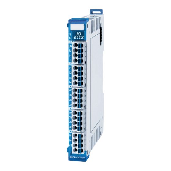
- Page 3 S-DIAS SMART MULTI I/O MODULE IO 011S S-DIAS Smart Multi I/O Module IO 011S with 6 digital inputs 8 digital back-readable short-circuit proof outputs 1 analog voltage input 1 analog current input The module has 6 digital inputs (+24 V/3.5 mA/1 µs) and 8 short-circuit proof digital, back-readable outputs (+24 V/0.5 A/150 µs).
-
Page 4: Table Of Contents
IO 011S S-DIAS SMART MULTI I/O MODULE Contents Introduction ................7 Target Group/Purpose of this Operating Manual ...... 7 Important Reference Documentation ......... 7 Contents of Delivery ..............7 Basic Safety Directives ............8 Symbols Used ................8 Disclaimer ..................10 General Safety Directives ............ - Page 5 S-DIAS SMART MULTI I/O MODULE IO 011S Environmental Conditions ............21 S-DIAS Protocol Version ............22 Mechanical Dimensions ............23 Connector Layout ..............24 Status LEDs ................. 25 Applicable Connectors ............... 25 Label Field ................... 26 Wiring ..................27 Wiring Example ................27 Guidelines for Digital Outputs ...........
- Page 6 IO 011S S-DIAS SMART MULTI I/O MODULE 11 Digital Output Operating Modes ...........36 11.1 Standard Mode ................36 11.2 Time-Trigger Mode ..............36 12 Analog Input Operating Modes ..........37 12.1 Standard Mode ................37 12.2 Time-Trigger Mode ..............37 12.3 Latch Mode ..................
- Page 7 S-DIAS SMART MULTI I/O MODULE IO 011S 18.1 Service ..................52 18.2 Repair ................... 52 19 Disposal ................. 52 20 Hardware Class IO011S ............53 20.1 Interfaces ..................54 20.1.1 General ................. 54 20.1.2 Digital Inputs and Outputs ............. 55 20.1.3...
- Page 8 IO 011S S-DIAS SMART MULTI I/O MODULE 20.6.1 Analog Values ................ 72 20.6.2 Digital Values ................. 72 Page 6 26.07.2023...
-
Page 9: Introduction
General knowledge of automation technology is required. Further help and training information, as well as the appropriate accessories can be found on our website www.sigmatek-automation.com. Our support team is happily available to answer your questions. Please see our website for our hotline number and business hours. -
Page 10: Basic Safety Directives
IO 011S S-DIAS SMART MULTI I/O MODULE Basic Safety Directives Symbols Used The following symbols are used in the operator documentation for warning and danger messages, as well as informational notes: DANGER Danger indicates that death or serious injury will occur, if the specified measures are not taken. - Page 11 S-DIAS SMART MULTI I/O MODULE IO 011S INFORMATION Information Provides important information on the product, handling or relevant sections of the documentation, which require attention. 26.07.2023 Page 9...
-
Page 12: Disclaimer
It does not guarantee properties under the warranty. Please thoroughly read the corresponding documents and this operating manual before handling a product. SIGMATEK GmbH & Co KG is not liable for damages caused through, non-compliance with these instructions or applicable regulations. -
Page 13: General Safety Directives
S-DIAS SMART MULTI I/O MODULE IO 011S General Safety Directives The Safety Directives in the other sections of this operating manual must be observed. These instructions are visually emphasized by symbols. INFORMATION According to EU Directives, the operating manual is a component of a product. -
Page 14: Software/Training
IO 011S S-DIAS SMART MULTI I/O MODULE CAUTION Handle the device with care and do not drop or let fall. Prevent foreign bodies and fluids from entering the device. The device must not be opened! Manipulez l’appareil avec précaution et ne le laissez pas tomber. -
Page 15: Standards And Directives
The product was constructed in compliance with the following European Union directives and tested for conformity. 3.1.1 EU Conformity Declaration EU Declaration of Conformity The product IO 011S conforms to the following European directives: • 2014/35/EU Low-voltage Directive • 2014/30/EU Electromagnetic Compatibility (EMC Directive) •... -
Page 16: Type Plate
IO 011S S-DIAS SMART MULTI I/O MODULE Type Plate HW: Hardware version SW: Software version Page 14 26.07.2023... -
Page 17: Technical Data
S-DIAS SMART MULTI I/O MODULE IO 011S Technical Data Digital Input Specifications Number Input voltage typically +24 V maximum +30 V Signal level low: < +8 V high: > +14 V Switching threshold typically +11 V Input current 3.7 mA at +24 V... -
Page 18: Digital Back-Readable Output Specifications
IO 011S S-DIAS SMART MULTI I/O MODULE Digital Back-Readable Output Specifications Number Short-circuit proof Maximum permissible continuous 0.5 A load current/channel Maximum total current 4 A (100% of on-time) (all 8 outputs) Maximum output braking energy maximum 1 Joule/channel (inductive load) ≤... -
Page 19: Analog Input Specifications
S-DIAS SMART MULTI I/O MODULE IO 011S ±10 V Analog Input Specifications Number of channels Measurement range -10 ... +10 V 0 ... +10 V -30.000 … +30.000 0 … +30.000 Measurement value With an open input, the firmware returns the positive maximum value and a... -
Page 20: Analog Current Input Specifications
IO 011S S-DIAS SMART MULTI I/O MODULE Analog Current Input Specifications Number of channels Measurement range 0-20 mA 4-20 mA Measurement value 0-60,000 12,000-60,000 With an open input, the firmware returns the positive maximum value and a status bit to indicate a cable... -
Page 21: Electrical Requirements
S-DIAS SMART MULTI I/O MODULE IO 011S Electrical Requirements Power supply +24 V 18-30 V DC Current consumption of +24 V corresponds to the load on the digital outputs power supply Voltage supply from S-DIAS bus +5 V Current consumption on the... - Page 22 IO 011S S-DIAS SMART MULTI I/O MODULE Page 20 26.07.2023...
-
Page 23: Miscellaneous
S-DIAS SMART MULTI I/O MODULE IO 011S Miscellaneous Article number 20-013-011S Standard UL 508 (E247993) in preparation Approvals cUL, CE, UKCA Environmental Conditions Storage temperature -20 ... +85 °C Environmental temperature 0 ... +60 °C Humidity 0-95 %, non-condensing Installation altitude above sea... -
Page 24: S-Dias Protocol Version
IO 011S S-DIAS SMART MULTI I/O MODULE S-DIAS Protocol Version For a correct function of the IO 011S, a S-DIAS protocol version v1.3.0 must be supported by the Master/Manager CPU. This is the case with: CP 101 since FPGA version v1.2 CP 102 since FPGA version v1.2... -
Page 25: Mechanical Dimensions
S-DIAS SMART MULTI I/O MODULE IO 011S Mechanical Dimensions 26.07.2023 Page 23... -
Page 26: Connector Layout
IO 011S S-DIAS SMART MULTI I/O MODULE Connector Layout Page 24 26.07.2023... -
Page 27: Status Leds
S-DIAS SMART MULTI I/O MODULE IO 011S Status LEDs Module Status green module active no supply available BLINKING (5 Hz) no communication User yellow can be set from the application (e.g. the module LED can be set to blinking through the... -
Page 28: Label Field
IO 011S S-DIAS SMART MULTI I/O MODULE Label Field Manufacturer Weidmüller Type MF 10/5 CABUR MC NE WS Article number Weidmüller 1854510000 Compatible printer Weidmüller Type Printjet Advanced 230V Article number Weidmüller 1324380000 Page 26 26.07.2023... -
Page 29: Wiring
S-DIAS SMART MULTI I/O MODULE IO 011S Wiring Wiring Example 26.07.2023 Page 27... -
Page 30: Guidelines For Digital Outputs
IO 011S S-DIAS SMART MULTI I/O MODULE Guidelines for Digital Outputs The fast digital inputs have a minimal input filter to provide a high time resolution. Due to the minimal input filtering, the inputs are more sensitive to noise than standard digital inputs. -
Page 31: Guidelines For Analog Inputs
S-DIAS SMART MULTI I/O MODULE IO 011S Guidelines for Analog Inputs The signals recorded by the analog modules are very small in comparison to the digital signals. To ensure error-free operation, a careful wiring method must be followed: The DIN rail must have an adequate mass connection. -
Page 32: Connection Of The Signal Source
IO 011S S-DIAS SMART MULTI I/O MODULE Connection of the Signal Source INFORMATION The common mode range of ±10 V must be obtained for each signal pin. Page 30 26.07.2023... -
Page 33: Connecting A 2-Wire Sensor
S-DIAS SMART MULTI I/O MODULE IO 011S Connecting a 2-Wire Sensor Connecting a 3-wire sensor 26.07.2023 Page 31... -
Page 34: Assembly/Installation
IO 011S S-DIAS SMART MULTI I/O MODULE Assembly/Installation Check Contents of Delivery Ensure that the contents of the delivery are complete and intact. See chapter 1.3 Contents of Delivery. INFORMATION On receipt and before initial use, check the device for damage. If the device is damaged, contact our customer service and do not install the device in your system. -
Page 35: Mounting
S-DIAS SMART MULTI I/O MODULE IO 011S Mounting The S-DIAS modules are designed for installation into the control cabinet. To mount the modules, a DIN-rail is required. The DIN rail must establish a conductive connection with the back wall of the control cabinet. The individual S-DIAS modules are mounted on the DIN rail as a block and secured with latches. - Page 36 IO 011S S-DIAS SMART MULTI I/O MODULE Recommended minimum distances of the S-DIAS modules to the surrounding components or control cabinet wall: a, b, c … distances in mm (inches) Page 34 26.07.2023...
-
Page 37: Digital Input/Back-Reading Output Operating Modes
S-DIAS SMART MULTI I/O MODULE IO 011S 10 Digital Input/Back-Reading Output Operating Modes The digital inputs and back-reading of the digital outputs can be operated in either Standard or latch mode. In latch mode, up to 128 registers can be assigned to the individual inputs. -
Page 38: Digital Output Operating Modes
IO 011S S-DIAS SMART MULTI I/O MODULE 11 Digital Output Operating Modes The digital outputs can be operated in either Standard or time-trigger mode. To define the time offset and the condition to set, 8x8 registers are available that can be distributed over the outputs as desired. -
Page 39: Analog Input Operating Modes
IO 011S 12 Analog Input Operating Modes The analog inputs of the IO 011S can be operated in either Standard mode, time-trigger mode or latch mode. This can be configured via bits 2 and 3 in the Info byte of the configuration data. -
Page 40: Latch Mode
IO 011S S-DIAS SMART MULTI I/O MODULE Correction within the firmware: If time-triggers are set values too close together, they are corrected (shifted) by the firmware wherever possible. If a correction is made, a “time- trigger corrected” bit is set for the control (HW class). -
Page 41: Synchronization With The Master Cpu
S-DIAS SMART MULTI I/O MODULE IO 011S 13 Synchronization with the Master CPU Since the minimum processing time of cyclic data is limited, but multiple sync/cycle times must be supported, there are various internal cycle times (ICT) depending on the S-DIAS Sync Interval (SDSI): 13.1 SDSI is Above/Equal to the Minimum ICT... -
Page 42: Addressing
14 Addressing 14.1 FPGA – HW Class Addressing Digital in and outputs are operated by the FPGA of the IO 011S directly. Whereby, a section of the address area is therefore required. This area is not used by the firmware. - Page 43 S-DIAS SMART MULTI I/O MODULE IO 011S Offset output register 8 (output X) 0012 Bit 14..0: Time offset in 1 µs Bit 15: Output value, which is set (low/high) Offset output register n Bit 14..0: Time offset in 1 µs...
- Page 44 IO 011S S-DIAS SMART MULTI I/O MODULE Latch register 2 (input X) 00C8 Bit 15: Edge indicator (1 = rising, 0 = falling) Bit14..0: Timestamp in 1 µs resolution Latch register n Bit 15: Edge indicator (1 = rising, 0 = falling) Bit14..0: Timestamp in 1 µs resolution...
-
Page 45: Firmware - Hw Class Addressing
S-DIAS SMART MULTI I/O MODULE IO 011S Output register multiplexer Bit 0: Enable offset output register for output 1 0218 Bit 7: Enable offset output register for output 8 (0 = not used, output register is assigned to output, 1= offset output register used, multiple offset output registers can be configured) 14.2 Firmware –... - Page 46 IO 011S S-DIAS SMART MULTI I/O MODULE 00C0 Cyclic Data for the HW Class Status Bit 0 24 V DC not OK Bit 1 not synchronized Bit 2 FLASH calibration checksum error Bit 3 FLASH calibration checksum error Bit 4...
- Page 47 S-DIAS SMART MULTI I/O MODULE IO 011S Measurement range testing (if default mode is active, the AIx measurement range bit applies and when Timeoffset mode is active, the TimeoffsetX bit applies) Bit 0 AI1 or Timeoffset 1 over range Bit 1...
- Page 48 IO 011S S-DIAS SMART MULTI I/O MODULE 01D6 Time Offset_AI or latch register 4 01D8 Time Offset_AI or latch register 5 01DA Time Offset_AI or latch register 6 01DC Time Offset_AI or latch register 7 0200 Firmware Configuration Data 0220...
- Page 49 S-DIAS SMART MULTI I/O MODULE IO 011S Configuration of the analog inputs Bit 0 analog input 1 0 … -10 V to +10 V 1 ... 0 V to +10 V Bit 1 analog input 2 0 … 0 mA to 20 mA 1 ...
- Page 50 IO 011S S-DIAS SMART MULTI I/O MODULE Distribution of the time offset register over inputs Bit 0-3 input assignment for register 1 0 … no input 1 … analog input 1 2 … analog input 2 3-15 … not allowed (interpreted as “no input”)
- Page 51 S-DIAS SMART MULTI I/O MODULE IO 011S Latch 2 – upper threshold value 0244 Latch 3 – lower threshold value 0246 Latch 3 – upper threshold value 0248 Latch 4 – lower threshold value 024A Latch 4 – upper threshold value 024C Latch 5 –...
-
Page 52: Supported Cycle Times
IO 011S S-DIAS SMART MULTI I/O MODULE 15 Supported Cycle Times 15.1 Cycle Times below 1 ms (in µs) x= supported 15.2 Cycle Times equal to or higher than 1 ms (in ms) x= supported x= supported Page 50 26.07.2023... -
Page 53: Transport/Storage
S-DIAS SMART MULTI I/O MODULE IO 011S 16 Transport/Storage INFORMATION This device contains sensitive electronics. During transport and storage, high mechanical stress must therefore be avoided. For storage and transport, the same values for humidity and vibration as for operation must be maintained! Temperature and humidity fluctuations may occur during transport. -
Page 54: Maintenance
IO 011S S-DIAS SMART MULTI I/O MODULE 18 Maintenance INFORMATION During maintenance as well as servicing, observe the safety instructions from chapter 2 Basic Safety Directives. 18.1 Service This product was constructed for low-maintenance operation. 18.2 Repair INFORMATION In the event of a defect/repair, send the device with a detailed error description to the address listed at the beginning of this document. -
Page 55: Hardware Class Io011S
S-DIAS SMART MULTI I/O MODULE IO 011S 20 Hardware Class IO011S IO011S for the S-DIAS multi I/O module IO011S This hardware class is used to control the RC 001 hardware module. The module has 6 digital inputs and 8 digital outputs (back-readable). In addition, 2 analog inputs are available. -
Page 56: Interfaces
IO 011S S-DIAS SMART MULTI I/O MODULE 20.1 Interfaces 20.1.1 General Class State State This server shows the actual status of the hardware class. Device ID State The device ID of the hardware module is shown in this server. FPGA Version State FPGA version of the module in 16#XY (e.g. -
Page 57: Digital Inputs And Outputs
S-DIAS SMART MULTI I/O MODULE IO 011S Time Offset State Bit 1 ... The time offset settings for the analog inputs were invalid and have Error Bits been adjusted by the firmware automatically. This can happen when the distance between two time offsets is too short (less than 15 µs). -
Page 58: Communication Interfaces
IO 011S S-DIAS SMART MULTI I/O MODULE AI[1-2] Property This value indicates the minimum value for the channel. If the minimum minimum value value is measured at the channel (depending on AI[1-2] config), this value is output in the software. The range of the measurement values are defined by the setting in the clients AI[1-2]_Min + AI[1-2]_Max. -
Page 59: Time Trigger - Mode
S-DIAS SMART MULTI I/O MODULE IO 011S 20.2 Time Trigger – Mode In Time Trigger mode, the output value is set to a defined time point. The configuration method must be called in during the Init for each digital output operated in the Time Trigger mode. -
Page 60: Hardware Time
IO 011S S-DIAS SMART MULTI I/O MODULE Important • A combination of the Time Trigger and Latch mode is not possible for the analog inputs. • The configuration methods must be called during the Init. • The methods for setting the time stamp and retrieving the values must be called from the realtime task. - Page 61 S-DIAS SMART MULTI I/O MODULE IO 011S Example 1, error: A digital output with 4 registers is configured. The output is turned on/off at 0 ms and 32 ms. Since the counter overflows at 32.7 ms, an additional on/off process is run.
- Page 62 IO 011S S-DIAS SMART MULTI I/O MODULE Example 2, correct: A digital output with 4 registers is configured. The output is turned off at 0 ms and 31 ms. The output is stopped with the Sync at 32 ms. No additional switching processes are triggered.
-
Page 63: Gethwtimestamp
S-DIAS SMART MULTI I/O MODULE IO 011S 20.4.1 GetHWTimeStamp Transfer parameters Type Description none Return parameters Type Description HWTimeStamp UINT Hardware time stamp in µs. This is based on the start of each realtime cycle. If the time stamp cannot be determined, the constant 0 is returned. -
Page 64: Global Methods
IO 011S S-DIAS SMART MULTI I/O MODULE 20.5 Global Methods The following method can be called via the ClassState server. 20.5.1 DigitalOut_ConfigTimeTrigger Transfer parameters Type Description OutputNr DINT Selects the digital output configured in the Time Trigger mode. Permissible values: 1-8... -
Page 65: Digitalout_Settimetrigger
S-DIAS SMART MULTI I/O MODULE IO 011S 20.5.2 DigitalOut_SetTimeTrigger Transfer parameters Type Description OutputNr DINT Selects the digital output specified by the Time Trigger switching time point. Permissible values: 1-8 SampleNr DINT Number of switching time points sent. ≤0 Current status of the output is stopped (HIGH, LOW) until this method is recalled. -
Page 66: Digitalin_Configlatch
IO 011S S-DIAS SMART MULTI I/O MODULE thereby be 10 ms in the future. The timestamp can be a maximum of 32767 µs (15 bits) minus the bus cycle time in the future. 20.5.3 DigitalIn_ConfigLatch Transfer parameters Type Description InputNr DINT Selects the digital input configured in Latch mode. -
Page 67: Digitalin_Getvalues
S-DIAS SMART MULTI I/O MODULE IO 011S 20.5.4 DigitalIn_GetValues Transfer parameters Type Description InputNr DINT Selects the digital input from which the value is back-read. Digital input 1-6 7-14 Back-reading of digital outputs 1.8 SampleNr DINT Number of measurement values to return Permissible values: 1-63 .. -
Page 68: Analogin_Configtimetrigger
IO 011S S-DIAS SMART MULTI I/O MODULE retval DINT Measurement values are valid. One of the input parameters “pDataTime”, -920 “pDataEdge” is NIL -921 The input was not configured in Latch mode. (See: “DigitalIn_ConfigLatch”) Input parameter “InputNr” exceeds the -922 allowed range. -
Page 69: Analogin_Configlatch
S-DIAS SMART MULTI I/O MODULE IO 011S Example configuration of the analog inputs: input 1 input 2 Total Allowed 20.5.6 AnalogIn_ConfigLatch Transfer parameters Type Description InputNr DINT Selects the analog input configured in Latch mode. Permissible values: 1-2 SampleNr DINT... - Page 70 IO 011S S-DIAS SMART MULTI I/O MODULE pUpperThreshold ^DINT Configures the upper limit at which to latch. The specified analog limits are converted via the analog input configuration. See: AI[1-2] Config Type, AI[1-2] minimal value, AI[1-2] maximal value. Pointer to the configuration:...
-
Page 71: Analogin_Settimetrigger
S-DIAS SMART MULTI I/O MODULE IO 011S 20.5.7 AnalogIn_SetTimeTrigger Transfer parameters Type Description InputNr DINT Selects the analog input specified in the Time Trigger measurement time point. Permissible values: 1-2 SampleNr DINT Number of measurement time points sent. Number of measurement time points sent. -
Page 72: Analogin_Getvalues
IO 011S S-DIAS SMART MULTI I/O MODULE 20.5.8 AnalogIn_GetValues Transfer parameters Type Description InputNr DINT Selects the analog input from which the values are back- read. Permissible values: 1-2 SampleNr DINT Number of measurement values to return. The maximum number of measurement... - Page 73 S-DIAS SMART MULTI I/O MODULE IO 011S pDataEdge ^BSINT Pointer to the measured edges. The input parameter is used in Latch mode only. The hardware class writes the measured edge information to this address. A “SampleNr” * 1-byte memory space must be provided.
-
Page 74: Time Response
IO 011S S-DIAS SMART MULTI I/O MODULE 20.6 Time Response 20.6.1 Analog Values 20.6.2 Digital Values Page 72 26.07.2023... - Page 75 S-DIAS SMART MULTI I/O MODULE IO 011S Documentation Changes Change date Affected page(s) Chapter Note 09.07.2019 1.9 S-DIAS Protocol Version Chapter added 21.10.2019 1.9 S-DIAS Protocol Version Note about operating system version added 14.11.2019 11 Supported Cycle Times Chapter added 28.02.2020...
Need help?
Do you have a question about the IO 011S and is the answer not in the manual?
Questions and answers