
Related Manuals for SIGMATEK SDI 101


Summary of Contents for SIGMATEK SDI 101
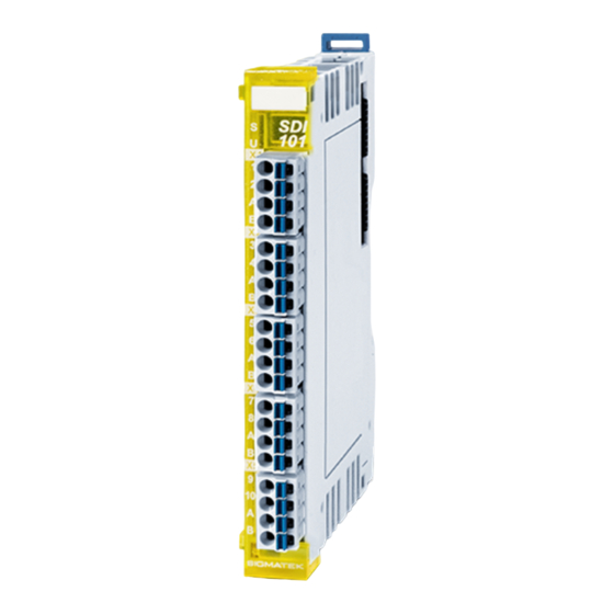
- Page 1 SDI 101 S-DIAS Safety Digital Input Module Date of creation: 18.12.2013 Version date: 02.12.2019 Article number: 20-891-101-E...
- Page 2 (print, photocopy, microfilm or in any other process) without the express permission. We reserve the right to make changes in the content without notice. The SIGMATEK GmbH & Co KG is not responsible for technical or printing errors in the handbook and assumes no responsibility for damages that occur...
- Page 3 Safety System Handbook, see homepage To use the SDI 101 in an application, a Safety CPU module that regulates the synchronized communication with the safety modules using safe bus telegrams is also required. This also includes •...
-
Page 4: Table Of Contents
SDI 101 S-DIAS SAFETY DIGITAL INPUT MODULE Contents Basic Safety Guidelines ............4 General Information on Safety ............ 4 Further Safety Guidelines ............5 General Requirements ..............6 Safety Conformity ..............10 Functional Safety Standards ............. 10 EU Conformity Declaration ............10 Safety-Relevant Parameters ............ - Page 5 S-DIAS SAFETY DIGITAL INPUT MODULE SDI 101 Wiring ..................22 Wiring Example ................22 Note ....................23 Mounting ................24 Supported Cycle Times ............26 Cycle Times below 1 ms (in µs) ..........26 Cycle Times equal to or higher than 1 ms (in ms) ....26 Disposal .................
-
Page 6: Basic Safety Guidelines
SDI 101 S-DIAS SAFETY DIGITAL INPUT MODULE Basic Safety Guidelines General Information on Safety If the safety guidelines are not followed, dangers to personnel can arise that could lead to serious injury or in worst cases, death. In less serious cases, systems and equipment can be damaged. -
Page 7: Further Safety Guidelines
S-DIAS SAFETY DIGITAL INPUT MODULE SDI 101 Further Safety Guidelines Warning, dangerous electrical voltage Avertissement d’une tension électrique dangereuse Hot surface warning Avertissement d’une surface chaude Danger for ESD-sensitive components Les signes de danger pour les composants sensibles aux décharges électrostatiques... -
Page 8: General Requirements
Before handling the product belonging to this documentation, Safety Guidelines the operating instructions and safety guidelines must be read. SIGMATEK GmbH & Co KG accepts no liability for damages resulting from non-compliance with the safety guidelines or the relevant regulations. - Page 9 S-DIAS SAFETY DIGITAL INPUT MODULE SDI 101 Qualified Personnel Installation, assembly, programming initial start-up, operation, maintenance and decommissioning of control and automation technology products in general, as well as safety- related products especially, can only be performed by qualified personnel.
- Page 10 SDI 101 S-DIAS SAFETY DIGITAL INPUT MODULE Designated Use The Safety modules are designed for use in safety-oriented applications and meet the required conditions for safety operation in compliance with Performance level e (PL e), in accordance with EN ISO 13849-1/-2 and SIL3 or SIL CL 3 in accordance with EN 62061.
- Page 11 S-DIAS SAFETY DIGITAL INPUT MODULE SDI 101 Operator Due Diligence The operator must ensure that • The Safety modules are to be used for their designated purpose only. • The Safety modules are to be operated in error-free, fully functional condition only.
-
Page 12: Safety Conformity
EN ISO 13849-2:2012 EU Conformity Declaration CE Declaration of Conformity The SDI 101 complies with the following European directives: • 2006/42/EG “Directive of the European Parliament and of the Council of 17 May 2006 on Machinery and Change to the Directive 95/16/EC”... -
Page 13: Safety-Relevant Parameters
S-DIAS SAFETY DIGITAL INPUT MODULE SDI 101 Safety-Relevant Parameters Input Module Safety Parameters Safety Level SDI 101 including CPU Single channel use: module SCP 011 / SCP = 2.23E-09 (1/h) PL d /Cat. 2 MTTF = 1829 years SIL 3 DC = 96.43 %... -
Page 14: Compatibility
SDI 101 S-DIAS SAFETY DIGITAL INPUT MODULE Compatibility Compatibility For compatibility of the S-DIAS Safety modules, see section "Compatibility of S-DIAS Safety Modules" in the system handbook. Test Signals for Cross-Circuit Detection The module sends pulses in cyclic time intervals to detect a crossed circuit in the outputs. -
Page 15: Technical Data
S-DIAS SAFETY DIGITAL INPUT MODULE SDI 101 Technical Data Input Specifications The inputs are Type 1 in accordance with EN 61131-2 Number Input voltage +24 V DC Input voltage range minimum +18 V maximum +30 V low: ≤ +5 V high: ≥... -
Page 16: Electrical Requirements
SDI 101 S-DIAS SAFETY DIGITAL INPUT MODULE Electrical Requirements Voltage supply from Safety bus +12 V Current consumption on the typically 12 mA maximum 15 mA Safety bus (+12 V supply) Voltage supply from Safety bus +24 V Current consumption on the... - Page 17 S-DIAS SAFETY DIGITAL INPUT MODULE SDI 101 02.12.2019 Page 15...
-
Page 18: Input Circuit
SDI 101 S-DIAS SAFETY DIGITAL INPUT MODULE Input Circuit Miscellaneous Article number 20-891-101 Hardware version 1.00 / 2.xx Standard UL 508 (E247993) Approbations UL, cUL, CE Page 16 02.12.2019... -
Page 19: Environmental Conditions
S-DIAS SAFETY DIGITAL INPUT MODULE SDI 101 Environmental Conditions Storage temperature -20 ... +85 °C Environmental temperature 0 ... +55 °C Humidity 0-95 %, non-condensing Installation altitude above sea 0-2000 m without derating level > 2000 m with derating of the maximum environmental temperature by 0.5 °C per 100 m... -
Page 20: Mechanical Dimensions
SDI 101 S-DIAS SAFETY DIGITAL INPUT MODULE Mechanical Dimensions Page 18 02.12.2019... -
Page 21: Connector Layout
S-DIAS SAFETY DIGITAL INPUT MODULE SDI 101 Connector Layout 02.12.2019 Page 19... -
Page 22: Status Leds
SDI 101 S-DIAS SAFETY DIGITAL INPUT MODULE Status LEDs Bus Status green bus communication OK no supply available BLINKING (5 Hz) no communication Safety-Used yellow module is used and no error module is not used or not in operational mode... -
Page 23: Label Field
S-DIAS SAFETY DIGITAL INPUT MODULE SDI 101 Label Field Manufacturer Weidmüller Type MF 10/5 CABUR MC NE WS Weidmüller article number 1854510000 Compatible printer Weidmüller Type Printjet Advanced 230V Weidmüller article number 1324380000 02.12.2019 Page 21... -
Page 24: Wiring
SDI 101 S-DIAS SAFETY DIGITAL INPUT MODULE Wiring Wiring Example Page 22 02.12.2019... -
Page 25: Note
S-DIAS SAFETY DIGITAL INPUT MODULE SDI 101 Note The input filters, which suppress noise signals, allow operation in harsh environmental conditions. A careful wiring method is also recommended to ensure error-free function. The following installation guidelines should be observed: •... -
Page 26: Mounting
SDI 101 S-DIAS SAFETY DIGITAL INPUT MODULE Mounting The S-DIAS modules are designed for installation into the control cabinet. To mount the modules a DIN-rail is required. The DIN rail must establish a conductive connection with the back wall of the control cabinet. The individual S-DIAS modules are mounted on the DIN rail as a block and secured with latches. - Page 27 S-DIAS SAFETY DIGITAL INPUT MODULE SDI 101 Recommended minimum distances of the S-DIAS modules to the surrounding components or control cabinet wall: a, b, c … distances in mm (inches) 02.12.2019 Page 25...
-
Page 28: Supported Cycle Times
S-DIAS SAFETY DIGITAL INPUT MODULE Supported Cycle Times The SDI 101 supports different cycle times. If variable sample points are deactivated, the IOs are updated with 4 kHz at cycle times of 250 µs to 32 ms. If the cycle time is lower than 250 µs, the IOs are updated with 3 kHz and PDO data are transmitted in a millisecond... - Page 29 S-DIAS SAFETY DIGITAL INPUT MODULE SDI 101 Documentation Changes Change date Affected Chapter Note page(s) 11.02.2014 5 Connector Layout Changed image 5.2 Applicable Connectors Connection capacity added French notes added 03.03.2014 5 Connector Layout Changed image 5.1 Status LEDs Changed/expanded Status LEDs table 01.04.2014...
- Page 30 SDI 101 S-DIAS SAFETY DIGITAL INPUT MODULE 02.04.2019 2.3 Safety-Relevant Correction of the safety-relevant parameters Parameters 3.6 Environmental Conditions Corrections environmental conditions Corrections due to CE 20.09.2019 2.3 Safety-Relevant Values adjusted Parameters 14.11.2019 8 Supported Cycle Times Chapter added 02.12.2019 2.3 Safety-Relevant...
Need help?
Do you have a question about the SDI 101 and is the answer not in the manual?
Questions and answers