Table of Contents
Advertisement
Quick Links
UM11035
LPCXpresso54608/54618/54S618 Board User Manual
Rev. 1.0 — 18 November 2016
Document information
Info
Keywords
Abstract
This datasheet has been downloaded from
Content
LPCXpresso54608, LPCXpresso54618, LPCXpresso54S618,
OM13092, OM13094, OM13095
LPCXpresso546xx User Manual
http://www.digchip.com
User manual
at this
page
Advertisement
Table of Contents

Related Manuals for NXP Semiconductors LPCXpresso54608


Summary of Contents for NXP Semiconductors LPCXpresso54608
- Page 1 UM11035 LPCXpresso54608/54618/54S618 Board User Manual Rev. 1.0 — 18 November 2016 User manual Document information Info Content Keywords LPCXpresso54608, LPCXpresso54618, LPCXpresso54S618, OM13092, OM13094, OM13095 Abstract LPCXpresso546xx User Manual This datasheet has been downloaded from http://www.digchip.com at this page...
- Page 2 UM11035 NXP Semiconductors LPCXpresso boards for LPC546xx family of MCUs Revision history Date Description 20161118 Initial revision Contact information For more information, please visit: http://www.nxp.com For sales office addresses, please send an email to: salesaddresses@nxp.com UM11035 All information provided in this document is subject to legal disclaimers.
-
Page 3: Fig 1. Lpcxpresso546Xx Underside View
The LPCXpresso™ family of boards provides a powerful and flexible development system for NXP's LPC Cortex®-M family of MCUs. They can be used with a wide range of development tools, including NXP’s MCUXpresso IDE. The LPCXpresso54608 (OM13092) / LPCXpresso54618 (OM13094) / LPCXpresso54S618 (OM13095) share the same design and have been developed by NXP to enable evaluation of and prototyping with the LPC546xx family of MCUs. -
Page 4: Feature Summary
UM11035 NXP Semiconductors LPCXpresso boards for LPC546xx family of MCUs 2. Feature summary The LPCXpresso546xx board includes the following features: On-board, high-speed USB based, Link2 debug probe with CMSIS-DAP and SEGGER J-Link protocol options: Link2 probe can be used with on-board LPC546xx or external target. -
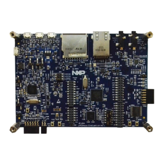
Page 5: Fig 2. Lpcxpresso546Xx Main Feature Layout
UM11035 NXP Semiconductors LPCXpresso boards for LPC546xx family of MCUs High speed Full speed Power USB port USB port (micro AB) (micro AB) (micro B) Ethernet Audio jacks (RJ45) SD/MMC socket Debug probe (micro B) Audio Ext. codec Debug Probe... -
Page 6: Fig 3. Jumper And Led Locations
UM11035 NXP Semiconductors LPCXpresso boards for LPC546xx family of MCUs JP10 SD/MMC card JP11 JP12 Power LED Debug probe Link2 boot LED DFU boot Reset LED Power LED Fig 3. Jumper and LED locations Table 1 lists the function of each jumper. - Page 7 UM11035 NXP Semiconductors LPCXpresso boards for LPC546xx family of MCUs Circuit ref Description Section Buffer Power Selection For On-board Target place in position 1-2 (default) For Off-board Target place in position 2-3 This header (not installed by default) provides a convenient...
- Page 8 UM11035 NXP Semiconductors LPCXpresso boards for LPC546xx family of MCUs Circuit ref Description Section This set of jumpers is used to configure 3.3V vs 1.8V board configurations. OM13092 boards are all 3.3V, so these jumpers schematic should not be changed from the default.
- Page 9 UM11035 NXP Semiconductors LPCXpresso boards for LPC546xx family of MCUs Table 2. LEDs, buttons and connectors Circuit Ref Description Section SD card slot power enable This LED illuminates when power is enabled to the SD card slot (controlled by LPC546xx port P2-5.)
- Page 10 UM11035 NXP Semiconductors LPCXpresso boards for LPC546xx family of MCUs Circuit Ref Description Section User button This button is connected to LPC546xx port pin P1-1, and is provided for user applications. Port P1-1 is pulled to ground when the button is pressed.
-
Page 11: Getting Started
UM11035 NXP Semiconductors LPCXpresso boards for LPC546xx family of MCUs Circuit Ref Description Section Peripheral expansion PMod connector 0.1” pitch 2x6 connector following the PMod standards. This connector is primarily intended for adding external peripherals using I C and/or SPI bus, but is also suitable for general purpose I/O connections. -
Page 12: Starting A Debug Session Using The On-Board (Link2) Debug Probe
UM11035 NXP Semiconductors LPCXpresso boards for LPC546xx family of MCUs a. Connect host computer to J3. Press and hold the ISP1 button while pressing and the releasing the Reset button. b. If using the high-speed port: connect host computer to J2. Press and hold the ISP2 button while pressing and the releasing the Reset button. -
Page 13: Installation Steps To Use Keil And Iar Tools
UM11035 NXP Semiconductors LPCXpresso boards for LPC546xx family of MCUs 3.2.2 Installation steps to use Keil and IAR tools 1. Download and install LPCScrypt or the Windows drivers for LPCXpresso boards (http://www.nxp.com/lpcutilities). This will install required drivers for the board. -
Page 14: What The Link2 Boot Led Indicates
UM11035 NXP Semiconductors LPCXpresso boards for LPC546xx family of MCUs development tools. This device is not intended for developer use, and should only be used with approved firmware images from NXP. The Link2 on-chip flash memory is factory programmed with a firmware image that supports CMSIS-DAP debug protocol, but also includes several other USB end point functions: ... -
Page 15: Fig 4. Identifying The Vcom Port
UM11035 NXP Semiconductors LPCXpresso boards for LPC546xx family of MCUs 4.2 Programming the Link2 firmware As mentioned earlier in this section, it is not normally necessary to program the Link2 firmware. However this can easily be accomplished using the supporting utility, LPCScrypt. -
Page 16: Lpcxpresso546Xx Current Measurement
UM11035 NXP Semiconductors LPCXpresso boards for LPC546xx family of MCUs the main external power is from the power only USB micro B-type connector (J1), or one of more of the USB device ports (USB0 at J3 or USB1 at J2), only the LPC546xx target and supporting devices and peripherals are powered. -
Page 17: Fig 5. Current Measurement Circuit Error
UM11035 NXP Semiconductors LPCXpresso boards for LPC546xx family of MCUs Due to input offset voltage variations in the MAX9634, the current measurement circuit is not recommended for measuring current below 150 uA. See Fig 5 as a guideline for measurement error versus measured current. -
Page 18: P3 Usart Header
UM11035 NXP Semiconductors LPCXpresso boards for LPC546xx family of MCUs port on the Link2 debug probe, which provides a bridging function to USB to a virtual com port (or “VCOM” port) on a host computer connected to the debug link connector, J8. On revision C boards TXD and RXD from this USART are also available at header P4, for an external serial connection to be made. -
Page 19: Device Mode
UM11035 NXP Semiconductors LPCXpresso boards for LPC546xx family of MCUs 6.2.1.2 Device mode The FS port supports USB device mode operation; no jumper settings are needed to configure this mode. When using the port in device mode, a standard micro USB cable can be used. -
Page 20: Host Expansion Header (J14)
UM11035 NXP Semiconductors LPCXpresso boards for LPC546xx family of MCUs 6.3 Host Expansion Header (J14) This header provides connectivity from the LPC546xx target to a remote Host, peripherals or other devices. Table 4 shows the connections. Table 4. Host Expansion Header signals... -
Page 21: Expansion Connectors (Including Arduino Connectivity)
UM11035 NXP Semiconductors LPCXpresso boards for LPC546xx family of MCUs Pin PMod standard connection J11 signal Flexcomm # / Port GPIO/RESET (out) GPIO/RESET (out) PIO3-11 GPIO/SCL 2 / PIO3-24 GPIO/SDA 2 / PIO3-23 VCC (3.3V) VDD (3.3V) Note that the I C and SPI ports on J11 are also connected to the Expansion connector J9, and the INT and RESET connections to J12. -
Page 22: Ethernet Port
UM11035 NXP Semiconductors LPCXpresso boards for LPC546xx family of MCUs Function Connector Shared with GPIO D8 J9 pin 19 Jumper (JP13) selection for USB0 FS host port. Only one of USB0 Host mode or GPIO function on this port may be used. -
Page 23: Fig 6. Line Input Circuitry
UM11035 NXP Semiconductors LPCXpresso boards for LPC546xx family of MCUs Note: The LCD data lines are shared with the PDM0 interface of the LPC546xx device (the LCD is enabled by default), and solder jumpers need to be modified to change between these configurations (see section for more details.) -
Page 24: Fig 7. Headphone / Line Output Circuitry
UM11035 NXP Semiconductors LPCXpresso boards for LPC546xx family of MCUs Fig 7. Headphone / line output circuitry The MCUXpresso SDK includes drivers and example code for the audio codec. 8.3 SD card The full size SD card (J7) includes in the LPCXpresso546xx board provides a 4-bit SDIO interface to support memory cards, plug-in WiFi modules, etc. -
Page 25: Legal Information
Semiconductors products in order to avoid a default of the applications and In no event shall NXP Semiconductors be liable for any indirect, incidental, the products or of the application or use by customer’s third party punitive, special or consequential damages (including - without limitation - customer(s). -
Page 26: Table Of Contents
UM11035 NXP Semiconductors LPCXpresso boards for LPC546xx family of MCUs 10. List of figures Fig 1. LPCXpresso546xx underside view ....3 Fig 2. LPCXpresso546xx main feature layout ..... 5 Fig 3. Jumper and LED locations ........ 6 Fig 4. Identifying the VCOM port ....... 15 Fig 5. -
Page 27: List Of Tables
UM11035 NXP Semiconductors LPCXpresso boards for LPC546xx family of MCUs 11. List of tables Table 1. Jumpers ............6 Table 2. LEDs, buttons and connectors ......9 Table 3. P4 connections ..........18 Table 4. Host Expansion Header signals ...... 20 Table 5. -
Page 28: Contents
UM11035 NXP Semiconductors LPCXpresso boards for LPC546xx family of MCUs 12. Contents 6.2.2.1 Mass Storage Boot (MSC) ........ 19 Introduction ............3 6.2.2.2 Host mode ............19 Feature summary ..........4 Host Expansion Header (J14) ......20 Board layout and settings ........4 PMod Slave Expansion Header ......
Need help?
Do you have a question about the LPCXpresso54608 and is the answer not in the manual?
Questions and answers