Table of Contents
Advertisement
Quick Links
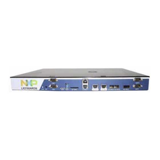
LX2160ARDBGSG
LX2160A Reference Design Board Getting Started Guide
Supports LX2160ARDB, Board Revisions B and C
Rev. 5 - 28 September 2021
1 Introduction
®
The Layerscape
LX2160A reference design board (RDB) provides a
comprehensive platform that enables design and evaluation of the Layerscape
LX2160A processor.
The LX2160ARDB functions with an integrated development environment
(IDE), such as CodeWarrior Development Studio. For instructions on how
to work with the CodeWarrior Development Studio IDE, see
Development Studio for LS series - ARM V8 ISA, Targeting
This document provides details of different board interfaces and explains how
to set up and boot the board.
2 Related documentation
The table below lists and explains the additional documents and resources that you can refer to for more information on the
LX2160ARDB. Some of the documents listed below may be available only under a non-disclosure agreement (NDA). To request
access to these documents, contact your local NXP field applications engineer (FAE) or sales representative.
Table 1. Related documentation
Document
LX2160A Reference Design Board
Reference Manual
LX2160A Reference Design Board
Errata
LX2160A Product Brief
LX2160A Data Sheet
LX2160A Reference Manual
LX2160A Chip Errata
LX2160A Design Checklist, AN5407 This document provides recommendations for new designs
CodeWarrior
Manual.
Description
Provides detailed description of the LX2160ARDB
Describes known errata and workarounds for the
LX2160ARDB
Provides a brief overview of the LX2160A processor
Provides information about electrical characteristics,
hardware design considerations, and ordering information
Provides a detailed description about the LX2160A multicore
processor and its features, such as memory map, serial
interfaces, power supply, chip features, and clock information
Lists the details of all known silicon errata for the LX2160A
based on the LX2160A. This document can also be used to
debug newly designed systems by highlighting those aspects
of a design that merit special attention during initial system
start-up.
Table continues on the next page...
Contents
1
Introduction......................................1
2
Related documentation................... 1
3
Hardware kit contents......................2
4
Chassis and board pictures.............3
5
Power and reset buttons................. 6
6
Connectors...................................... 6
7
Jumpers...........................................8
8
DIP switches..................................10
9
LEDs..............................................13
10
...................................................... 16
11
Troubleshooting............................ 22
12
Revision history............................. 22
Link / how to access
LX2160ARDBRM.pdf
LX2160ARDBE.pdf
LX2160APB.pdf
LX2160A.pdf
LX2160ARM.pdf
Contact NXP FAE /
sales representative
AN5407.pdf
User Guide
Advertisement
Table of Contents

Related Manuals for NXP Semiconductors LX2160ARDBGSG


Summary of Contents for NXP Semiconductors LX2160ARDBGSG
-
Page 1: Table Of Contents
LX2160ARDBGSG LX2160A Reference Design Board Getting Started Guide Supports LX2160ARDB, Board Revisions B and C Rev. 5 — 28 September 2021 User Guide Contents 1 Introduction Introduction........1 Related documentation....1 ® The Layerscape LX2160A reference design board (RDB) provides a Hardware kit contents......2... -
Page 2: Hardware Kit Contents
NXP Semiconductors Hardware kit contents Table 1. Related documentation (continued) Document Description Link / how to access Layerscape Software Development Describes how to work with LSDK, which is a complete Linux LSDKUG.pdf Kit User Guide kit for NXP Layerscape Arm-based SoCs and the reference and evaluation boards available for them. -
Page 3: Chassis And Board Pictures
NXP Semiconductors Chassis and board pictures Table 3. LX2RDBKIT1-10-40 kit contents (continued) Item description Manufacturer Manufacturing part For port/slot Quantity number nm wavelength, 150 m maximum reach QSFP+ LAN optical 12FMPOOM3 - 66239 40G MAC2 cable, multi-mode, OM3 50/125, MPO... - Page 4 NXP Semiconductors Chassis and board pictures Power jack Figure 2. Chassis back panel The figure below shows the onboard connectors of the LX2160ARDB. J26 J27 J25 J24 J44 J54 J34 J35 J10 Figure 3. Connectors The figure below shows the jumpers, LEDs, and DIP switches available on the LX2160ARDB.
- Page 5 NXP Semiconductors Chassis and board pictures D39-D28 D44-D45 D43-D42 D27-D24 D23-D18 SW4-SW1 Figure 4. Jumpers, LEDs, and DIP switches The figure below shows a closer look of the DIP switches. Figure 5. DIP switches LX2160A Reference Design Board Getting Started Guide, Rev. 5, 28 September 2021...
-
Page 6: Power And Reset Buttons
NXP Semiconductors Power and reset buttons 5 Power and reset buttons The power and reset buttons are present on the front panel of the LX2160ARDB chassis (see Figure 1). Both power and reset buttons are push buttons. The table below describes the power and reset buttons. - Page 7 NXP Semiconductors Connectors Table 6. LX2160ARDB connectors (continued) Connector Connector type Description Typical connection QSFP+ cage 40G MAC2: 40 Gbit Accepts one zQSFP+ transceiver (optical or Ethernet copper) (not included in the hardware kit) SFP cage (2) 25G MAC5/6: 25 Gbit...
-
Page 8: Jumpers
NXP Semiconductors Jumpers Table 6. LX2160ARDB connectors (continued) Connector Connector type Description Typical connection 1x3-pin header I2C1 Provides remote access to I2C1 bus 1x3-pin header I2C1_CH0 Provides remote access to I2C1 channel 0 segment 1x3-pin header I2C1_CH1 Provides remote access to I2C1 channel 1... - Page 9 NXP Semiconductors Jumpers Table 7. LX2160ARDB jumpers Jumper Type Name/function Description 1x2-pin connector TA_BB_TMP_DETECT_B enable Open: TA_BB_TMP_DETECT_B pin is grounded Shorted: TA_BB_TMP_DETECT_B pin is powered (default setting) 1x2-pin connector VBAT power for TA_BB_VDD Not supported. Do not install J7. See...
-
Page 10: Dip Switches
NXP Semiconductors DIP switches 8 DIP switches The LX2160ARDB provides dual inline package (DIP) switches to allow easy configuration of the system for the most popular board options. These switches are stored in BRDCFG and DUTCFG registers by CPLD before being used, allowing software (either local or remote) to reconfigure the system as needed. - Page 11 NXP Semiconductors DIP switches Table 8. Switch settings (continued) Switch Supported function Description SW2[2] (board CS4223 configuration SW_INIT40GE revision B) CFG_40GE_ROM • 0: CS4223 40 GbE PHY is not self-configured (default setting) • 1: CS4223 40 GbE PHY is self-configured on reset...
- Page 12 NXP Semiconductors DIP switches Table 8. Switch settings (continued) Switch Supported function Description Reserved with 000 as the default settings NOTE Do not change the default settings of this switch. SW3[8] Unused Reserved with 0 as the default setting SW4[1]...
-
Page 13: Leds
NXP Semiconductors LEDs 9 LEDs The LX2160ARDB has numerous onboard light-emitting diodes (LEDs), which can be used to monitor various system functions, such as power on, reset, board faults, and so on. The information collected from LEDs can be used for debugging purposes. The table below lists all the LEDs present on the LX2160ARDB. - Page 14 NXP Semiconductors LEDs Table 10. LX2160ARDB LEDs (continued) Reference LED color LED name Description (when LED is ON) designator Green Green Green Green Green Green 3VSB The ATX power supply is supplying 3.3 V “standby power” to the system. The system cannot power up unless this supply is provided.
- Page 15 NXP Semiconductors LEDs Table 11. LED array functions If FAIL LED is OFF If FAIL LED is ON Startup (power on to Normal behavior Fault code power-up complete) "Idle" pattern, a pattern shown If FAIL LED is ON and M[7:0] are not blinking,...
-
Page 16: Getting Started With Lx2160Ardb
NXP Semiconductors Getting started with LX2160ARDB Table 12. Power Sequencer state (continued) State LED: M[7:4] Description EN_TIER3 0011 = 0x3 Enable tier 3 PSUs, wait for tier 3 power-good reports EN_TIER4 0100 = 0x4 Enable tier 4 PSUs, wait for tier 4 power-good reports... - Page 17 NXP Semiconductors Getting started with LX2160ARDB 10.1 Prerequisites To set up your LX2160ARDB, you need the items listed in the table below. Table 14. Prerequisites Item Available in Purpose / required action board kit? Hardware Host computer system capable of...
- Page 18 NXP Semiconductors Getting started with LX2160ARDB Figure 6. Power supply connection NOTE As a precautionary step, the power switch mounted on the wall (if available) must be turned off before connecting the power cord. 5. Turn on the wall mount power switch. The D28 LED (3VSB) turns ON when the standby power is available (see figure below).
- Page 19 NXP Semiconductors Getting started with LX2160ARDB 6. Connect one end of the DB9 female to DB9 female cable to the UART1 port available on chassis front panel (see figure below) and the other end of the cable to the USB-to-serial adapter. Connect the other end of the USB-to-serial adapter to the USB port of the host machine.
- Page 20 NXP Semiconductors Getting started with LX2160ARDB 8. Optionally, connect the Ethernet cable if you want to connect your board to the network, for example, for obtaining latest board software and updating board images. 9. Set up Tera Term on the host computer: a.
- Page 21 NXP Semiconductors Getting started with LX2160ARDB Model: NXP Layerscape LX2160ARDB Board Board: LX2160ACE Rev2.0-RDB, Board version: C, boot from FlexSPI DEV#0 FPGA: v9.0 SERDES1 Reference: Clock1 = 161.13MHz Clock2 = 161.13MHz SERDES2 Reference: Clock1 = 100MHz Clock2 = 100MHz SERDES3 Reference: Clock1 = 100MHz Clock2 = 100MHz...
-
Page 22: Troubleshooting
NXP Semiconductors Troubleshooting 11 Troubleshooting This section explains the basic troubleshooting tips for the LX2160ARDB. U-Boot log not displaying Perform the following steps in case console is not showing any print: • Ensure that the board is configured for the default switch settings, as described in Table •... - Page 23 NXP Semiconductors Revision history Table 15. Revision history (continued) Revision Date Topic cross-reference Change description Booting LX2160ARDB Added new boot log Rev. 2 30 June 2019 DIP switches Reformatted Table 9 to improve readability Multi-status LEDs Updated Table 11 Removed software-related sections (Ethernet port...
- Page 24 Right to make changes - NXP Semiconductors reserves the right to make changes to information published in this document, including without limitation specifications and product descriptions, at any time and without notice.
Need help?
Do you have a question about the LX2160ARDBGSG and is the answer not in the manual?
Questions and answers