Advertisement
AN13215
Introduction to Boundary Scan of i.MX8/i.MX8X
Rev. 0 - 04/2021
by:
NXP Semiconductors
1 Introduction
The i.MX 8/i.MX 8X families provide the boundary scan feature according to the
IEEE1149.1 specification via the JTAG controller.
The boundary scan is a method for checking the interconnections on PCBs and
internal IC sub-blocks. The mechanism is defined in the IEEE1149.1 standard.
2 Purpose
This application note shows how to use a Boundary Scan Description Language (BSDL) file associated with a Lauterbach
debugger to set all i.MX8 IOs into a known state through the boundary scan. When this is achieved, the proper IO state can be
checked using a multimeter to ensure there is no issue with the board.
This document focuses on entering the boundary scan mode for the board-level test. It provides the setup sequence and script
examples to ensure first-pass success.
The engineers should be familiar with the standard for the test access port and boundary scan architecture from the IEEE
1149.1 specification.
3 Overview
3.1 Boundary scan
The boundary scan technique allows the signals at component boundaries to be controlled and observed through the shift-register
stage associated with each pad. Each stage is a part of a larger boundary scan register cell, and cells for each pad are
interconnected serially to form a shift-register chain around the border of the design. This register can be used to read and write
port states.
In the normal mode, these cells are transparent and the core is connected to the ports. In the boundary scan mode, the core is
isolated from the ports and the port signals are controlled by the JTAG interface.
Figure 1
shows the JTAG controller block with the associated signals and exported registers. For more details, see the IEEE
1149.1 specification and the i.MX 8/i/MX 8X reference manuals.
Contents
1
Introduction......................................1
2
Purpose........................................... 1
3
Overview......................................... 1
4
Software setup................................ 2
5
Hardware setup............................... 3
6
debugger......................................... 6
7
Revision history............................. 10
Application Note
Advertisement
Table of Contents

Related Manuals for NXP Semiconductors i.MX8


Summary of Contents for NXP Semiconductors i.MX8
-
Page 1: Table Of Contents
This application note shows how to use a Boundary Scan Description Language (BSDL) file associated with a Lauterbach debugger to set all i.MX8 IOs into a known state through the boundary scan. When this is achieved, the proper IO state can be checked using a multimeter to ensure there is no issue with the board. -
Page 2: Software Setup
"Download" menu option and then into the "TRACE32 Software" menu option. Introduction to Boundary Scan of i.MX8/i.MX8X, Rev. 0, 04/2021 Application Note 2 / 11... -
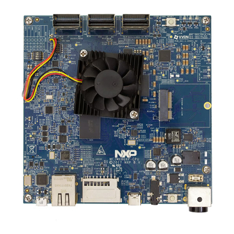
Page 3: Hardware Setup
For example, see how the Lauterbach probe is connected to the i.MX8QXP MEK board in Figure 1. Connect the Lauterbach JTAG debugger to the EVK board through the 10-pin JTAG interface. Introduction to Boundary Scan of i.MX8/i.MX8X, Rev. 0, 04/2021 Application Note 3 / 11... - Page 4 Under these conditions, the TEST_MODE signal must be set to low and the POR_B must be set to high. The boot selecting DIP switches must be set to the "Serial Download Mode". Introduction to Boundary Scan of i.MX8/i.MX8X, Rev. 0, 04/2021 Application Note...
- Page 5 NXP Semiconductors Hardware setup Figure 4. BOOT selection switches In the i.MX8QXP MEK board schematics, notice the following: • The TEST_MODE signal is always low. Introduction to Boundary Scan of i.MX8/i.MX8X, Rev. 0, 04/2021 Application Note 5 / 11...
-
Page 6: Boundary Scan Using I.mx 8/I.mx 8 Bsdl File And Lauterbach Jtag Debugger
Therefore, the power supply pin for each specific module must be powered for the IO buffers to operate. This is straightforward for the digital pins within the system. The boundary scan is as follows: Introduction to Boundary Scan of i.MX8/i.MX8X, Rev. 0, 04/2021 Application Note 6 / 11... - Page 7 — BSDL.state Figure 8. TRACE32 software • The "BSDL.state" command opens a new window. Click the “FILE” button and load the BSDL file you want to validate. Introduction to Boundary Scan of i.MX8/i.MX8X, Rev. 0, 04/2021 Application Note 7 / 11...
- Page 8 Figure 11. BSDL.state window • Click the “SAMPLEall” button and the “No result” entry changes to “Test done”. Then double-click the entity name and the "BSDL.SET" window appears. Introduction to Boundary Scan of i.MX8/i.MX8X, Rev. 0, 04/2021 Application Note 8 / 11...
- Page 9 UART2_RX and UART2_TX are set to UART2_RX = output 1, UART2_TX = output 1 (if it exists). Then switch to the "BSDL.state" window and check the “SetAndRun” and “TwoStepDR” checkboxes. Introduction to Boundary Scan of i.MX8/i.MX8X, Rev. 0, 04/2021 Application Note...
-
Page 10: Revision History
NXP Semiconductors Revision history Figure 14. “SetAndRun” and “TwoStepDR” checkboxes 7 Revision history Table 2. Revision history Revision number Date Substantive changes 04/2021 Initial release Introduction to Boundary Scan of i.MX8/i.MX8X, Rev. 0, 04/2021 Application Note 10 / 11... - Page 11 Right to make changes - NXP Semiconductors reserves the right to make changes to information published in this document, including without limitation specifications and product descriptions, at any time and without notice. This document supersedes and replaces all information supplied prior to the publication hereof.
Need help?
Do you have a question about the i.MX8 and is the answer not in the manual?
Questions and answers