Table of Contents
Advertisement
Quick Links
Arrow.com.
Downloaded from
UM11035
LPCXpresso546x8/540xx/54S0xx Board User Manual
Rev. 2.1 — 7th January 2019
Document information
Info
Content
Keywords
LPCXpresso54608, LPCXpresso54618, LPCXpresso54628,
LPCXpresso54018, LPCXpresso54S018
OM13092, OM13094, OM13098, OM13099, OM40003, LPC54S018-EVK
Abstract
LPCXpresso546x8/540xx/LPC54S0xx User Manual
User manual
Advertisement
Table of Contents

Related Manuals for NXP Semiconductors LPCXpresso54608


Summary of Contents for NXP Semiconductors LPCXpresso54608
- Page 1 UM11035 LPCXpresso546x8/540xx/54S0xx Board User Manual Rev. 2.1 — 7th January 2019 User manual Document information Info Content Keywords LPCXpresso54608, LPCXpresso54618, LPCXpresso54628, LPCXpresso54018, LPCXpresso54S018 OM13092, OM13094, OM13098, OM13099, OM40003, LPC54S018-EVK Abstract LPCXpresso546x8/540xx/LPC54S0xx User Manual Arrow.com. Downloaded from...
- Page 2 UM11035 NXP Semiconductors LPCXpresso boards for LPC546xx/LPC540xx/LPC54S0xx families of MCUs Revision history Date Description 20190719 Added LPCXpresso54S018, modified title. Added Troubleshooting section, added links to various sections in Table 1. 20180112 Added LPCXpresso54018, modified title 20170525 Added LPCXpresso54628, included reference to OM13099.
-
Page 3: Introduction
The LPCXpresso™ family of boards provides a powerful and flexible development system for NXP's LPC Cortex®-M family of MCUs. They can be used with a wide range of development tools, including NXP’s MCUXpresso IDE. The LPCXpresso54608 (OM13092), LPCXpresso54618 (board provided as part of the OM13094 CAN-FD Kit),... -
Page 4: Fig 1. Lpcxpresso546X8/540Xx/54S0Xx Underside View
CAN-FD shield supplied in the OM13094 kit (this shield board is also available as a standalone product, order code OM13099.) This shield board can be used with any of the LPCXpresso boards described, but note that the LPCXpresso54608 does not support CAN-FD. -
Page 5: Board Layout And Settings
UM11035 NXP Semiconductors LPCXpresso boards for LPC546xx/LPC540xx/LPC54S0xx families of MCUs • 3 x user LEDs • Target Reset, ISP (3) and user buttons • Expansion options based on popular standards: Arduino UNO compatible expansion site with additional LPCXpresso V3 standard connections ... -
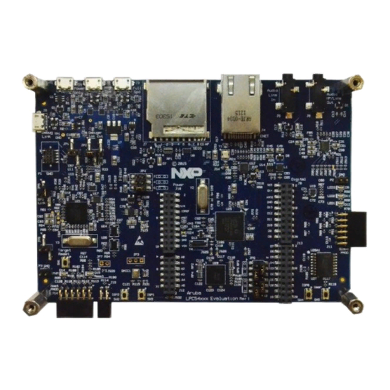
Page 6: Fig 2. Lpcxpresso546X8/540Xx/54S0Xx Main Feature Layout
UM11035 NXP Semiconductors LPCXpresso boards for LPC546xx/LPC540xx/LPC54S0xx families of MCUs High speed Full speed Power USB port USB port (micro B) (micro AB) (micro AB) Ethernet Audio jacks (RJ45) SD/MMC socket Debug probe (micro B) Audio Ext. codec Debug Probe... -
Page 7: Fig 3. Jumper And Led Locations
UM11035 NXP Semiconductors LPCXpresso boards for LPC546xx/LPC540xx/LPC54S0xx families of MCUs JP10 SD/MMC card JP11 JP12 Power LED Debug probe Link2 boot LED DFU boot Reset LED Power LED Fig 3. Jumper and LED locations Table 1 lists the function of each jumper. - Page 8 UM11035 NXP Semiconductors LPCXpresso boards for LPC546xx/LPC540xx/LPC54S0xx families of MCUs Circuit ref Description Section Buffer Power Selection For On-board Target place in position 1-2 (default) For Off-board Target place in position 2-3 This header (not installed by default) provides a convenient...
- Page 9 UM11035 NXP Semiconductors LPCXpresso boards for LPC546xx/LPC540xx/LPC54S0xx families of MCUs Circuit ref Description Section JP7 may be fitted to provide a convenient way to enable/disable (not the reset signal to/from the expansion connectors. Solder jumper schematic installed by JS28 should be removed if JP7 is to be used.
- Page 10 UM11035 NXP Semiconductors LPCXpresso boards for LPC546xx/LPC540xx/LPC54S0xx families of MCUs Table 2 describes the board LED and button functions, and connectors. Table 2. LEDs, buttons and connectors Circuit Ref Description Section SD card slot power enable This LED illuminates when power is enabled to the SD card slot (controlled by LPC546x8/540xx/54S0xx port P2-5.)
- Page 11 UM11035 NXP Semiconductors LPCXpresso boards for LPC546xx/LPC540xx/LPC54S0xx families of MCUs SW2, SW3, ISP / User buttons These switches can be used to force the LPC546x8/540xx/54S0xx in to ISP boot modes, as shown below. Note that ISP boot is also affected by OTP bit settings, and behavior will also be modified based on port activity as the boot ROM executes.
- Page 12 UM11035 NXP Semiconductors LPCXpresso boards for LPC546xx/LPC540xx/LPC54S0xx families of MCUs Circuit Ref Description Section pins when the EMC bus has been initialized, since these pins are shared with the EMC D2-D3 pins, and the SDRAM chip select may float at reset.
-
Page 13: Getting Started
LCD panel. 3. Getting Started The LPCXpresso54608 and LPCXpresso54628 boards are pre-programmed with a demo application showcasing Embedded Wizard from TARA Systems (note that some older stock may contain a demonstration from a different vendor). Connect a micro USB cable from connector J8 or J1 to a power source (computer or power supply) and the board will boot within a few seconds and run this demonstration. -
Page 14: Loading Applications Using Usb Mass Storage Boot (Msc Class) Mode (Lpcxpresso546X8 Boards Only)
UM11035 NXP Semiconductors LPCXpresso boards for LPC546xx/LPC540xx/LPC54S0xx families of MCUs flash utility or Flash Magic). The demo binary packages mentioned earlier include instructions on using these tools. 3.1 Loading applications using USB mass storage boot (MSC class) mode (LPCXpresso546x8 boards only) The LPC546xx device family supports mass storage boot mode, enabling “drag and... -
Page 15: Installation Steps For Use With Mcuxpresso Ide
UM11035 NXP Semiconductors LPCXpresso boards for LPC546xx/LPC540xx/LPC54S0xx families of MCUs For further information and tutorial videos please visit the Getting Started tab on the landing page for the board being used. Each board’s landing page can be found at the URL https://www.nxp.com/demoboard/<board-name>... -
Page 16: Installation Steps To Use Keil And Iar Tools
UM11035 NXP Semiconductors LPCXpresso boards for LPC546xx/LPC540xx/LPC54S0xx families of MCUs 3.2.2 Installation steps to use Keil and IAR tools 1. Download and install LPCScrypt or the Windows drivers for LPCXpresso boards (http://www.nxp.com/lpcutilities). This will install required drivers for the board. - Page 17 UM11035 NXP Semiconductors LPCXpresso boards for LPC546xx/LPC540xx/LPC54S0xx families of MCUs The Link2 Debug Probe is implemented using an LPC432x MCU (circuit reference U21), which provides a high speed USB port interface to the host computer that runs the development tools. This device is not intended for developer use, and should only be used with approved firmware images from NXP.
-
Page 18: Fig 4. Identifying The Vcom Port
UM11035 NXP Semiconductors LPCXpresso boards for LPC546xx/LPC540xx/LPC54S0xx families of MCUs 4.1 What the Link2 boot LED indicates LED D10 is the Link2 MCU BOOT0_LED indicator. This LED reflects the state of Link2 MCU pin P1_1. When the boot process fails, D1 will toggle at a 1 Hz rate for 60 seconds. -
Page 19: Configuring The
UM11035 NXP Semiconductors LPCXpresso boards for LPC546xx/LPC540xx/LPC54S0xx families of MCUs 4.4 Configuring the LPCXpresso546x8/540xx/54S0xx to debug an external target The LPCXpresso546x8/540xx/54S0xx board’s Link2 Debug Probe may be used to debug an off-board target MCU. The on-board Link2 Debug Probe is capable of debugging target MCU’s with a VDDIO range of 1.6V to 3.6V. -
Page 20: Lpcxpresso546X8/540Xx/54S0Xx Current Measurement
UM11035 NXP Semiconductors LPCXpresso boards for LPC546xx/LPC540xx/LPC54S0xx families of MCUs 6.1 LPCXpresso546x8/540xx/54S0xx current measurement The LPC546x8/540xx/54S0xx current can be measured by measuring the voltage across a sense resistor in series with the supply, a current meter or using the on board current measurement circuit. -
Page 21: Fig 5. Current Measurement Circuit Error
UM11035 NXP Semiconductors LPCXpresso boards for LPC546xx/LPC540xx/LPC54S0xx families of MCUs the Link2 processor and is not user programmable. Power measurement utilities to use this feature are available in LPCXpresso and IDE MCUXpresso IDE installations. Due to input offset voltage variations in the MAX9634, the current measurement circuit is not recommended for measuring current below 150 uA. -
Page 22: P3 Usart Header
UM11035 NXP Semiconductors LPCXpresso boards for LPC546xx/LPC540xx/LPC54S0xx families of MCUs On LPCXpresso546x8/540xx/54S0xx boards the USART from Flexcomm0 supports ISP UART mode booting and is used by default for semi-hosting debug messages. This USART is connected to a serial port on the Link2 Debug Probe, which provides a bridging function to USB to a virtual com port (or “VCOM”... -
Page 23: Device Mode
UM11035 NXP Semiconductors LPCXpresso boards for LPC546xx/LPC540xx/LPC54S0xx families of MCUs this mode press and hold down the ISP1 button while pressing and releasing the reset button (or power cycling the board). See Section for further information on how to use this mode. -
Page 24: Host Expansion Header (J14)
UM11035 NXP Semiconductors LPCXpresso boards for LPC546xx/LPC540xx/LPC54S0xx families of MCUs (Note: Although not required for the HS USB port operation, it is recommended to check JP11, JP12 and JP13 have a jumper in position 1-2 to enable Ethernet operation and availability of the I/O at the Expansion connector D8.) -
Page 25: Expansion Connectors (Including Arduino Connectivity)
UM11035 NXP Semiconductors LPCXpresso boards for LPC546xx/LPC540xx/LPC54S0xx families of MCUs Pin PMod standard connection J11 signal Flexcomm # / Port GPIO/SPI-MOSI out / UART TXD out GPIO/SPI-MOSI in/out 9 / PIO3-21 GPIO/SPI-MISO in / UART RXD in GPIO/SPI-MISO out/in 9 / PIO3-22... -
Page 26: Ethernet Port
UM11035 NXP Semiconductors LPCXpresso boards for LPC546xx/LPC540xx/LPC54S0xx families of MCUs Below shows the sharing of signals between the expansion connectors and other connectors or circuit functions. Refer to the board schematics for more details. Table 7. Expansion Connector signal sharing... -
Page 27: Other Board Features
This section describes board functions not mentioned elsewhere in this document. 9.1 LCD with capacitive touch The LPCXpresso54608/54628/54018 include a Rocktech RK043FN02H-CT color LCD display panel with a resolution of 272x480 pixels and a capacitive touch controller. The LCD and capacitive touch controller interface to the main board via flex cables routed beneath the LCD panel. -
Page 28: Fig 6. Line Input Circuitry
UM11035 NXP Semiconductors LPCXpresso boards for LPC546xx/LPC540xx/LPC54S0xx families of MCUs Fig 6. Line input circuitry A second 3.5 mm stereo jack socket (J6) provides a headphone / line out from the codec, via the circuit shown in Fig 7. Headphone / line output circuitry The MCUXpresso SDK includes drivers and example code for the audio codec. -
Page 29: Accelerometer
(product number OM13099). This board features the NXP TJA1059 dual transceiver, plus an RS232C transceiver. This shield board is also compatible with all the LPCXpresso546x8/540xx/54S0xx boards (although LPCXpresso54608 only supports classic CAN, not CAN-FD.) 10.1 Board layout and jumpers Fig 8 shows the Shield board layout. -
Page 30: Fig 8. Can-Fd Shield Layout
UM11035 NXP Semiconductors LPCXpresso boards for LPC546xx/LPC540xx/LPC54S0xx families of MCUs Fig 8. CAN-FD Shield Layout The CAN-FD Shield has a double-height DB9 connector installed by default (P3) for CAN/CAN-FD connections. The Shield board layout includes provision for a DB9 connector to be installed (P2) but a standard 0.1”... -
Page 31: Installation
UM11035 NXP Semiconductors LPCXpresso boards for LPC546xx/LPC540xx/LPC54S0xx families of MCUs Circuit ref Description Default LPCXpresso546x8/540xx/54S0xx boards A4 is connected to pin PIO2_17. Install these jumpers to provide termination on CAN/CAN-FD JP3 & JP4 Installed connection 2. JP5 & JP6 Install these jumpers to provide termination on CAN/CAN-FD Installed connection 2. -
Page 32: Legal Information
Semiconductors products in order to avoid a default of the applications and In no event shall NXP Semiconductors be liable for any indirect, incidental, the products or of the application or use by customer’s third party punitive, special or consequential damages (including - without limitation - customer(s). -
Page 33: Table Of Contents
UM11035 NXP Semiconductors LPCXpresso boards for LPC546xx/LPC540xx/LPC54S0xx families of MCUs 12. List of figures Fig 1. LPCXpresso546x8/540xx/54S0xx underside view ..............4 Fig 2. LPCXpresso546x8/540xx/54S0xx main feature layout ..............6 Fig 3. Jumper and LED locations ........ 7 Fig 4. Identifying the VCOM port ....... 18 Fig 5. -
Page 34: List Of Tables
UM11035 NXP Semiconductors LPCXpresso boards for LPC546xx/LPC540xx/LPC54S0xx families of MCUs 13. List of tables Table 1. Jumpers ............7 Table 2. LEDs, buttons and connectors ......10 Table 3. P4 connections ..........22 Table 4. Host Expansion Header signals ...... 24 Table 5. -
Page 35: Contents
UM11035 NXP Semiconductors LPCXpresso boards for LPC546xx/LPC540xx/LPC54S0xx families of MCUs 14. Contents 7.1.1 P3 USART header ..........22 Introduction ............3 USB ports ............22 Feature summary ..........4 7.2.1 USB full-speed port (USB0) ......22 Board layout and settings ........5 7.2.1.1... - Page 36 UM11035 NXP Semiconductors LPCXpresso boards for LPC546xx/LPC540xx/LPC54S0xx families of MCUs 11.2 Trademarks ............32 List of figures ............. 33 List of tables ............34 Contents ............. 35 Please be aware that important notices concerning this document and the product(s) described herein, have been included in the section 'Legal information'.
Need help?
Do you have a question about the LPCXpresso54608 and is the answer not in the manual?
Questions and answers