Table of Contents
Advertisement
Quick Links
Advertisement
Table of Contents

Related Manuals for thomann the t.racks 8x8 Matrix


Summary of Contents for thomann the t.racks 8x8 Matrix
- Page 1 8x8 Matrix Controller...
- Page 2 Thomann GmbH Hans-Thomann-Straße 1 96138 Burgebrach Germany Telephone: +49 (0) 9546 9223-0 Internet: www.thomann.de 04.12.2023, ID: 490507 (V2)
-
Page 3: Table Of Contents
Table of contents Table of contents General information..........................5 1.1 Symbols and signal words....................... 5 Safety instructions............................. 7 Features................................9 Installation and starting up........................ 10 Connections and controls........................15 Operating..............................18 6.1 Remote control protocol (RS232)....................44 Technical specifications........................61 Protecting the environment...................... - Page 4 8x8 Matrix Controller...
-
Page 5: General Information
Our products and documentation are subject to a process of continuous development. They are therefore subject to change. Please refer to the latest version of the documentation, which is ready for download under www.thomann.de. 1.1 Symbols and signal words In this section you will find an overview of the meaning of symbols and signal words that are used in this document. - Page 6 General information Warning signs Type of danger Warning – high-voltage. Warning – danger zone. 8x8 Matrix Controller...
-
Page 7: Safety Instructions
Safety instructions Safety instructions Intended use This device is intended to be used for amplification, mixing and playback of signals from musical instruments and microphones. Use the device only as described in this user manual. Any other use or use under other operating conditions is considered to be improper and may result in personal injury or property damage. - Page 8 Safety instructions DANGER! Danger to life due to electric current! Within the device there are areas where high voltages may be present. Never remove any covers. There are no user-serviceable parts inside. Do not use the device when covers, safety equipment or optical components are missing or damaged. NOTICE! Risk of fire due to covered vents and neighbouring heat sources! If the vents of the device are covered or the device is operated in the immediate vicinity of other heat sources, the device can over‐...
-
Page 9: Features
Features Features Special features of the device: Digital 8x8 matrix processor 96 kHz sampling rate 32 bit DSP 24 bit AD/DA converter Inputs: 8 mono channels (screw terminal block) for microphone and line level signals Outputs: 8 mono channels (screw terminal) for line level signals Comprehensive setting options for optimal sound –... -
Page 10: Installation And Starting Up
Installation and starting up Installation and starting up Unpack and check carefully there is no transportation damage before using the unit. Keep the equipment packaging. To fully protect the product against vibration, dust and moisture during transportation or storage use the original packaging or your own packaging material suitable for transport or storage, respectively. - Page 11 Installation and starting up Configuration example 1 The figure schematically shows how the device can be controlled via a computer's USB port. 8X8 Matrix USB Cable Computer 8x8 Matrix Controller...
- Page 12 Installation and starting up Configuration example 2 The illustrations show schematically how one device or several devices can be integrated into a local area network (LAN). Computer ID 1 8 8 X X 8 8 M M a a t t r r i i x x 8x8 Matrix Controller...
- Page 13 Installation and starting up WIFI Router Computer ID 1 8 8 X X 8 8 M M a a t t r r i i x x ID 2 8 8 X X 8 8 M M a a t t r r i i x x 8x8 Matrix Controller...
- Page 14 Installation and starting up Configuration example 3 The illustrations show schematically how a device can be configured via the serial port. 8 8 X X 8 8 M M a a t t r r i i x x Computer 8x8 Matrix Controller...
-
Page 15: Connections And Controls
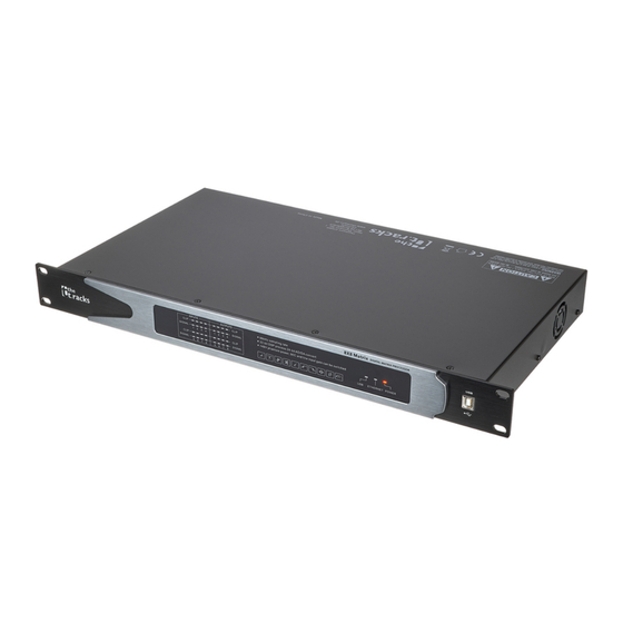
Connections and controls Connections and controls Front panel 8X8 Matrix ö 8x8 Matrix Controller... - Page 16 Connections and controls 1 [INPUTS] [SIGNAL] | Level display for the input channels. [CLIP] | Clipping indicator. In this case, the level of the input signal is too high. 2 [OUTPUTS] [SIGNAL] | Level display for the output channels. [CLIP] | Clipping indicator. In this case, the level of the output signal is too high. 3 Control LEDs [USB] | The LED lights up when a signal is received via the USB connection.
- Page 17 Connections and controls Rear panel 8 8 X X 8 8 M M a a t t r r i i x x & 5 Rubber panel plug with fuse holder for power supply 6 [POWER] | Main switch. Turns the device on and off. 7 [ETHERNET] | RJ45 socket as LAN connection for connection to your network 8 [RS232/485 PORT] | Serial interface for remote control of the device or cascading of several devices, designed as screw terminal block...
-
Page 18: Operating
Operating Operating The device can be controlled with the supplied software. The connection from the PC to the device can be established via USB, LAN or the serial interface. If you connect several devices via a switch, you have to assign a different IP address to each device and set a different ID code. - Page 19 Operating Install and start the software. Connect the device to the power grid. Insert the software CD into the disk drive of your Windows PC and start the installation programme that matches the device version. Follow the instructions of the installation programme to completion. Connect your PC to the device and switch on the device at the main switch.
- Page 20 Operating Open the PC programme. The programme automatically detects the connected device. ð In the upper right corner of the programme window the marking ‘Online’ appears. 8x8 Matrix Controller...
- Page 21 Operating 8x8 Matrix Controller...
- Page 22 Operating Exit software Click on the ‘Online’ button in the programme window. Close the programme window. 8x8 Matrix Controller...
- Page 23 Operating Components of the programme All tabs of the programme window have a similar structure and are divided into the following window areas: ö & Tab for selecting a function group Main menu Button for the status of the connection to the PC 8x8 Matrix Controller...
- Page 24 Operating Display area Control area Buttons for quick access to important presets 8x8 Matrix Controller...
- Page 25 Operating Main menu Menu item Meaning ‘File’ Loading user presets and saving them on the PC ‘Link’ Linking input and output channels Example: Link input and output channels, e.g. to form a stereo group. ‘Copy’ Copying parameter settings from one input or output channel to another ‘Lock’...
- Page 26 Operating Buttons for quick access to Range Meaning important presets Number Number of the current user's preset Name Name of the current user's preset Store Saving user preset Recall Recalling user preset 8x8 Matrix Controller...
- Page 27 Operating ‘Gain’ tab 8x8 Matrix Controller...
- Page 28 Operating Range Meaning Display area The waveform of input and output channels is graphically displayed. Use the radio buttons ‘Inx’ and ‘Outx’ to determine the inputs and outputs to be displayed. Control area Drag the faders with the mouse to adjust the levels for the input and output channels.
- Page 29 Operating ‘Gate’ tab 8x8 Matrix Controller...
- Page 30 Operating Range Meaning Display area Shows the current settings of the noise gate for the respective channel, with a symbolic level indicator symbol appearing next to it for the input channels. The red dot in the curve corresponds to the current signal. Control area Drag the faders with the mouse to set the noise gate parameters for all input and output channels: Threshold, Attack, Release...
- Page 31 Operating ‘Comp’ tab 8x8 Matrix Controller...
- Page 32 Operating Range Meaning Display area Shows the current settings of the compressor function for the respective output channel, with a symbolic level indicator symbol appearing next to it for all output channels. The red dot in the curve corresponds to the cur‐ rent signal.
- Page 33 Operating ‘Delay’ tab 8x8 Matrix Controller...
- Page 34 Operating Range Meaning Display area Shows the set delays for all in and output channels. Control area Drag the faders with the mouse to adjust the delay for the respective channel. Click on one of the buttons ‘ms’ , ‘m’ or ‘ft’ to select the unit used.
- Page 35 Operating ‘Matrix’ tab 8x8 Matrix Controller...
- Page 36 Operating Range Meaning Display area Shows the current interconnection of input to output channels. Input and output channels can be renamed. Click on a function area (e.g. ‘Gain’ or ‘Gate’ ) to open the tab where you can enter the relevant param‐ eters directly.
- Page 37 Operating ‘Aux’ tab 8x8 Matrix Controller...
- Page 38 Operating Range Meaning Display area Select ‘Mag’ to set the ‘PEQ’ , high pass, and low pass parameters. Select ‘Phase’ to set the phase curve. You can also synchronously display the parametric equalizer and the phase curve of a channel that is not cur‐ rently selected.
- Page 39 Operating Range Meaning Select: Selection of input channels 1 to 8 for mixing into Aux channels Gain: Aux gain, mute and level indicators for Aux channels 8x8 Matrix Controller...
- Page 40 Operating ‘In’ tab 8x8 Matrix Controller...
- Page 41 Operating Range Meaning Display area Use the radio buttons ‘Mag’ or ‘Phase’ to switch the diagram from Carte‐ sian coordinates (level vs. frequency) to polar coordinates (angle vs. fre‐ quency). Use the radio button ‘SHOW ALL EQ’ to show the parameters for all the frequency bands.
- Page 42 Operating ‘Out’ tab 8x8 Matrix Controller...
- Page 43 Operating Range Meaning Display area Use the radio buttons ‘Mag’ or ‘PHASE’ to switch the diagram from Carte‐ sian coordinates (level vs. frequency) to polar coordinates (angle vs. fre‐ quency). Use the radio button ‘SHOW ALL EQ’ to show the parameters for all the frequency bands.
-
Page 44: Remote Control Protocol (Rs232)
Operating 6.1 Remote control protocol (RS232) Control Package Format Device Data1 Data2 Data3 Addres Packet 0×7B 0×7D 1…254 0×40… 0×?? 0×?? 0×?? 0×7D 0×7B 0×5C Command Detail Tab. 1: Load Preset Matrix (0×40) Device Fac‐ Preset 0×00 Addres tory/ User Packet 0×7B 0×7D... - Page 45 Operating Tab. 2: Gain Control (0×41) Device In/Out Chann +/– Addres Packet 0×7B 0×7D 1…254 0×41 In:0, 00…15 +:0, –:1 0×7D 0×7B Out:1 Example (In1 Gain +): 7B7D01410000007D7B Tab. 3: Mute Control (0×42) Device In/Out Chann No/Yes STX Addres Packet 0×7B 0×7D 1…254 0×42...
- Page 46 Operating Tab. 4: Load Preset Control (0×43) Device Fac‐ Preset 0×00 Addres tory/ User Packet 0×7B 0×7D 1…254 0×43 F:0, U:1 0…12 0×7D 0×7B Example (Recall user's preset U01): 7B7D01430100007D7B Tab. 5: Input Volume Control (0×44) Device Chann HI-VOL LO- Addres Packet 0×7B...
- Page 47 Operating Tab. 6: Output Volume Control (0×45) Device Chann HI-VOL LO- Addres Packet 0×7B 0×7D 1…254 0×45 00…15 0×?? 0×?? 0×7D 0×7B Example (Set Out2 Volume -3.0dB): 7B7D01450100FA7D7B Tab. 7: Sub Volume Control (0×46) Device In/Out Gain 0×00 Addres Packet 0×7B 0×7D 1…254 0×46...
- Page 48 Operating Tab. 8: Sub Gain Control (0×47) Device In/Out +/– 0×00 Addres Packet 0×7B 0×7D 1…254 0×47 In:0, +:0, –:1 0 0×7D 0×7B Out:1 Example (Sub Input Gain+): 7B7D01470000007D7B Tab. 9: Get Now Gain (0×48) Device In/Out Chann 0×00 Addres Packet 0×7B 0×7D...
- Page 49 Operating Tab. 10: Get Now Mute (0×49) Device In/Out Chann 0×00 Addres Packet 0×7B 0×7D 1…254 0×49 In:0, 00…15 0 0×7D 0×7B Out:1 MCU Return: 1st Byte: In/Out, 2nd Byte = Channel, 3rd Byte: 0x00 or 0x01 = Un-Mute or Mute Example (Read In1 mute parameter): 7B7D01490000007D7B Tab.
- Page 50 Operating Tab. 12: Get Now Sub (0×4B) Device In/Out 0×00 0×00 Addres Packet 0×7B 0×7D 1…254 0×4B In:0, 0×7D 0×7B Out:1 MCU Return: 1st Byte: 0 … 100%, 2nd Byte = 0x00 or 0x01 = Un-Mute or Mute Example (Read Sub Input parameter): 7B7D014B0000007D7B Tab.
- Page 51 Operating Tab. 14: Get Now Level (0×4D) Device In/Out Chann 0×00 Addres Packet 0×7B 0×7D 1…254 0×4D In:0, 00…15 0 0×7D 0×7B Out:1, Aux: 2 MCU Return: 1st Byte: In/Out, 2nd Byte = Channel, 3rd Byte: -128 … –1, 0… +127dB = 0x80 … 0xFF, 0x00 …...
- Page 52 Operating Example (Out4 Matrix In2 On): 7B7D014E0301017D7B Tab. 16: Get Matrix (0×4F) Device Chann 0×00 Addres Packet 0×7B 0×7D 1…254 0×4F 00…15 00…15 0 0×7D 0×7B MCU Return: 0x00 or 0x01 = Off or On Example (Read Out3 Matrix In3 Parameter ): 7B7D014F0202007D7B Tab.
- Page 53 Operating Tab. 18: Aux Mute Control (0×52) Device 0×00 No/Yes STX Addres Packet 0×7B 0×7D 1…254 0×52 0×02 0×00 No:0, 0×7D 0×7B Yes:1 Example (Aux Mute): 7B7D01520200017D7B Tab. 19: Aux Volume Control (0×53) Device HI-VOL LO- Addres Packet 0×7B 0×7D 1…254 0×53 0×02 0×??
- Page 54 Operating Tab. 20: Volume Step Control (0×54) Device In/Out Chann +/– Addres Packet 0×7B 0×7D 1…254 0×54 In:0, 00…15 +:0, –:1 0×7D 0×7B Out:1 –60dB…–20dB: 2dB/Step, –20dB…+12dB: 1dB/Step Example (Volume): 7B7D01540000007D7B 8x8 Matrix Controller...
- Page 55 Operating Tab. 21: Aux On Off Control(0×55) Device 0…02 Select On / off STX Addres Packet 0×7B 0×7D 1…254 0×55 0×02 0: Off 0×7D 0×7B Camer 1:On 2: Auto Effect Example (Aux Camera On): 7B7D01550201017D7B Example (Aux AutoMix On): 7B7D01550202017D7B Example (Aux Effect On): 7B7D01550200017D7B 8x8 Matrix Controller...
- Page 56 Operating Tab. 22: Aux CH Select Control (0×56) Device Select Ch 8… Addres 16…9 Packet 0×7B 0×7D 1…254 0×56 0: AUX Bit0… Bit0… 0×7D 0×7B Bit7: Bit7: Camer 0: No 0: No 1: Yes 1: Yes 2: Auto Example (Aux In1&In3): 7B7D01560000057D7B Example (Aux Camera In2&In4): 7B7D015601000A7D7B Example (Aux Auto Mix In5&In6): 7B7D01560200307D7B 8x8 Matrix...
- Page 57 Operating Tab. 23: FBQ Control (0×57) Device 0×00 Chann Addres Packet 0×7B 0×7D 1…254 0×57 0×00 00…15 0:Off 0×7D 0×7B 1… 4:Level Example (In3 FBQ Level3): 7B7D01570002037D7B Tab. 24: Get Aux Now Gain (0×58) Device 0×00 0×00 Addres Packet 0×7B 0×7D 1…254 0×58 0×02...
- Page 58 Operating Tab. 25: Get Aux Now Mute (0×59) Device 0×00 0×00 Addres Packet 0×7B 0×7D 1…254 0×59 0×02 0×00 0×00 0×7D 0×7B MCU Return: 1st Byte: Aux/Effect, 2nd Byte: 0x00 or 0x01 = Un-Mute or Mute Example (Get Aux Mute): 7B7D01590200007D7B Tab.
- Page 59 Operating Example (Get Effect): 7B7D015B0200007D7B Tab. 27: Get Aux Now Ch Select (0×5C) Device 0×02 Select 0×00 Addres Packet 0×7B 0×7D 1…254 0×5C 0×02 0:Aux 0×00 0×7D 0×7B 1:Came 2:Auto MCU Return: 1st Byte: Select, 2nd Byte: Matrix Example (Get Aux Ch Select): 7B7D015C0200007D7B 8x8 Matrix Controller...
- Page 60 Operating Tab. 28: Get Aux Now FBQ (0×5E) Device 0×00 Chann Addres Packet 0×7B 0×7D 1…254 0×5E 0×00 0…15 0:Off 0×7D 0×7B 1… 4:Level MCU Return: 1st Byte: Channel, 2nd Byte = Level Example (Get In5 FBQ ): 7B7D015E0004007D7B Communication Parameter Baud Rate 115 200 Data Bit...
-
Page 61: Technical Specifications
Technical specifications Technical specifications Input connections Power supply Rubber panel plug C14 USB interface USB-B RJ45 Serial interface D-sub Audio signal Type Screw terminal block Level (Line) +18 dBu (max.) Gain (Line) 35 dBu (max.) Gain (Mic) 50 dBu (max.) Impedance (Line) >10 kΩ... - Page 62 Technical specifications Total harmonic distortion (THD) < 0.005% (1 kHz, 0 dBu) Signal-to-noise ratio > 115 dBu Common-mode rejection ratio (CMRR) > 75 dBu (1 kHz) Crosstalk > 70 dBu (20 Hz … 20 kHz) Digital signal processing Digital signal processor 32 bit A/D-D/A converter 24 bit...
- Page 63 Technical specifications Further information 2-way stereo 3-way stereo Digital Delay Number of frequency bands Number of mono input channels Number of stereo input channels Number of output channels Compressor Gate 2-channel Attack/Release adjustable Tube 8x8 Matrix Controller...
- Page 64 Technical specifications Block diagram GAIN GATE HP/LP XOVER GAIN COMP PHASE DELAY MUTE Out1 GAIN GATE HP/LP XOVER GAIN COMP PHASE DELAY MUTE Out2 GAIN GATE HP/LP XOVER GAIN COMP PHASE DELAY MUTE Out3 GAIN GATE HP/LP XOVER GAIN COMP PHASE DELAY MUTE...
-
Page 65: Protecting The Environment
Protecting the environment Protecting the environment Disposal of the packaging mate‐ rial For the transport and protective packaging, environmentally friendly materials have been chosen that can be supplied to normal recycling. Ensure that plastic bags, packaging, etc. are properly disposed of. Do not just dispose of these materials with your normal household waste, but make sure that they are collected for recycling. - Page 66 Notes 8x8 Matrix Controller...
- Page 68 Musikhaus Thomann · Hans-Thomann-Straße 1 · 96138 Burgebrach · Germany · www.thomann.de...
Need help?
Do you have a question about the the t.racks 8x8 Matrix and is the answer not in the manual?
Questions and answers