Table of Contents
Advertisement
Quick Links
Video-inserter
VL1-MBN4
Compatible with Mercedes Benz vehicles
with Comand APS HD NTG3, Comand APS NTG4,
Audio20 NTG4 and Audio50 APS NTG4
navigation systems
with 10pin LVDS connector on the monitor
Video-inserter with 2 video + 1 rear-view camera input and CAN control
Product features
Video-inserter for factory-infotainment monitors
1 CVBS Rear-view camera video-input
2 CVBS video-inputs for after-market devices (e.g. DVD-Player, DVB-T tuner, ...)
Automatic switching to rear-view camera input on engagement of reverse gear
Video-in-motion (ONLY for connected video-sources)
Video-inputs PAL/NTSC compatible
Version 02.08.2022
HW: 16-(V65)
VL1-MBN4
Advertisement
Table of Contents

Related Manuals for NavLinkz VL1-MBN4


Summary of Contents for NavLinkz VL1-MBN4
- Page 1 Video-inserter VL1-MBN4 Compatible with Mercedes Benz vehicles with Comand APS HD NTG3, Comand APS NTG4, Audio20 NTG4 and Audio50 APS NTG4 navigation systems with 10pin LVDS connector on the monitor Video-inserter with 2 video + 1 rear-view camera input and CAN control Product features ...
-
Page 2: Table Of Contents
Audio-switch and audio-insertion 2.5.3 After-market rear-view camera 2.5.3.1 Connection – video signal of the rear-view camera Connection - video-interface and external keypad Picture settings 3. Interface operation 4. Specifications 5. Frequently asked questions 6. Technical Support Version 02.08.2022 HW: 16-(V65) VL1-MBN4... -
Page 3: Prior To Installation
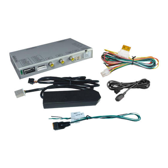
Technical knowledge is necessary for installation. The place of installation must be free of moisture and away from heat sources. 1.1. Delivery contents Take down the serial number of the interface and store this manual for support purposes: ____________________ Version 02.08.2022 HW: 16-(V65) VL1-MBN4... -
Page 4: Checking The Compatibility Of Vehicle And Accessories
Connectors – Video interface The video-interface converts the connected after-market sources video signals to an LVDS signal which is the inserted into the factory monitor on certain trigger options. Version 02.08.2022 HW: 16-(V65) VL1-MBN4... -
Page 5: Dip-Switch Settings
4 options, retry and disconnected the 6pin power plug of the video- box between every change of the dip setting. Version 02.08.2022 HW: 16-(V65) VL1-MBN4... -
Page 6: Installation
If power source is not taken directly from the battery, the connection has to be checked for being start-up proven and permanent. 2.1. Place of installation The interface is installed on the backside of the vehicle’s monitor. Version 02.08.2022 HW: 16-(V65) VL1-MBN4... -
Page 7: Connection Scheme
2.2. Connection scheme Version 02.08.2022 HW: 16-(V65) VL1-MBN4... -
Page 8: Connection - 6Pin Interface Cable
Note: The connection of the green wire (Reverse signal) will be described in chapter “After-market rear-view camera”. The white wire, can be used by +12V impulse to switch the enabled video sources , same as the keypad (see chapter “video interface- operation”). Version 02.08.2022 HW: 16-(V65) VL1-MBN4... -
Page 9: Connection - The Factory Monitor
Pay attention to a correct connection of the 10 pins inside! Connect the female 10pin LVDS connector to the previously become free 10pin LVDS connector of the factory monitor Version 02.08.2022 HW: 16-(V65) VL1-MBN4... -
Page 10: Connection - Video Sources
Connect video RCA of the AV-source 1 to the female RCA connector AV 1 of the video interface. Connect video RCA of the AV-source 2 to the female RCA connector AV 2 of the video interface. Version 02.08.2022 HW: 16-(V65) VL1-MBN4... -
Page 11: Audio-Switch And Audio-Insertion
AUX input). When switching the video interface from AV1 to AV2, the audio signal is also switched automatically. Attention: The audio cable CAB-FV-AUDIO shown in the diagram is not included in the delivery contents and is optionally available! Version 02.08.2022 HW: 16-(V65) VL1-MBN4... - Page 12 Audio input signal R/L of source AV1 Audio output signal R/L for factory audio AUX or FM-modulator Ground Attention: The audio cable CAB-FV-AUDIO shown in the diagram is not included in the delivery contents and is optionally available! Version 02.08.2022 HW: 16-(V65) VL1-MBN4...
-
Page 13: After-Market Rear-View Camera
Connect the reverse light’s power cable to the relay’s white coloured cable “Reverse light”. Connect +12V permanent battery power to the relay’s green coloured input cable “BATT”. Connect the relay’s black coloured Power cable “GND” and the rear-view camera’s negative cable both to the vehicle’s negative Ground. Version 02.08.2022 HW: 16-(V65) VL1-MBN4... -
Page 14: Connection - Video Signal Of The Rear-View Camera
CAM. Note: Picture settings for CAM input must be done in AV2. 2.6. Connecting video-interface and keypad Connect the female 4pin Microfit connector of the keypad to the male 4pin Microfit connector of the video-interface. Version 02.08.2022 HW: 16-(V65) VL1-MBN4... -
Page 15: Picture Settings
Note: The OSD menu is only shown when a working video source is connected to the selected video-input of the interface. The following settings are available: Brightness Contrast Saturation Position H (horizontal) Position V (vertical) Version 02.08.2022 HW: 16-(V65) VL1-MBN4... -
Page 16: Specifications
170mA @12V Video input 0.7V - 1V Video input formats PAL/NTSC RGB-Video amplitude 0.7V with 75 Ohm impedance Temperature range -40°C to +85°C Dimensions video-box 152 x 21 x 90 mm (W x H x D) Version 02.08.2022 HW: 16-(V65) VL1-MBN4... - Page 17 Camera input picture fluorescent light which shines Test camera under natural light outside the garage. flickers. directly into the camera. Camera input picture is Protection sticker not Remove protection sticker from lens. bluish. removed from camera lens. Version 02.08.2022 HW: 16-(V65) VL1-MBN4...
-
Page 18: Technical Support
6pin to 8pin cable and isolate both ends. Technical Support Please note that direct technical support is only available for products purchased directly from NavLinkz GmbH. For products bought from other sources, contact your vendor for technical support. NavLinkz GmbH...
Need help?
Do you have a question about the VL1-MBN4 and is the answer not in the manual?
Questions and answers