
Related Manuals for Advantech ITA-260 Series


Summary of Contents for Advantech ITA-260 Series
- Page 1 User Manual ITA-260 Series Fanless Embedded High Performance Compact Industrial Computer 嵌入式無風扇電腦...
- Page 2 No part of this manual may be reproduced, copied, translated or transmitted in any form or by any means without the prior written permission of Advantech Co., Ltd. Information provided in this manual is intended to be accurate and reliable. How- ever, Advantech Co., Ltd.
- Page 3 Because of Advantech’s high quality-control standards and rigorous testing, most of our customers never need to use our repair service. If an Advantech product is defec- tive, it will be repaired or replaced at no charge during the warranty period. For out- of-warranty repairs, you will be billed according to the cost of replacement materials, service time and freight.
- Page 4 Advantech has come to be known. Your satisfaction is our primary concern. Here is a guide to Advantech's customer services.
- Page 5 RoHS Claim 設備名稱:電腦 型號(型式): 260 型號參見說明書 Equipment name Type designation (Type) 限用物質及其化學符號 Restricted substances and its chemical symbols 六價鉻 多溴聯苯 多溴二苯醚 單元 鉛 汞 鎘 Lead Mercury Cadmium Hexavalent Polybrominated Polybrominated chromium biphenyls diphenyl ethers 電路板 — 外殼 — 線材 —...
- Page 6 Warnings, Cautions, and Notes Warning! Warnings indicate conditions, which if not observed, can cause personal injury! Caution! Cautions are included to help you avoid damaging hardware or losing data. e.g. There is a danger of a new battery exploding if it is incorrectly installed. Replace the battery only with the same or equivalent type recom- mended by the manufacturer.
- Page 7 Advantech doesn’t provide power component for this product, users should pur- chase power components with CCC certificate.This product is intended to be...
- Page 8 DISCLAIMER: This set of instructions is given according to IEC 704-1. Advantech disclaims all responsibility for the accuracy of any statements contained herein. Safety Precaution - Static Electricity Follow these simple precautions to protect yourself from harm and the products from damage.
-
Page 9: Table Of Contents
Contents Chapter Overview..........1 Introduction ....................2 Specifications .................... 2 Power Information ..................2 Table 1.1: Power ................. 2 Environmental Specifications ..............3 Table 1.2: Environmental Specifications ........3 Dimension Diagram................... 4 Figure 1.1 Dimension Diagram of ITA-260........ 5 Exploded Diagram..................6 Figure 1.2 Exploded Diagram of ITA-260........ - Page 10 3.1.5 Installing the DIN Rail Bracket ............24 3.1.6 Installing Expansion Module ............25 Figure 3.6 Installing expansion Module ........25 Chapter BIOS..........30 Introduction ..................... 30 Figure 4.1 Setup Program Initial Screen ........30 Entering Setup ..................31 Figure 4.2 Press <DEL> to Enter Setup ........31 4.2.1 Main Setup..................
-
Page 11: Chapter 1 Overview
Chapter Overview This chapter provides general Information about the ITA-260. -
Page 12: Introduction
Introduction The ITA-260 is a fanless compact industrial computer chassis with Intel 11th Gen eration Processor and wide voltage input range, which is speciallydesigned for i ntelligent transportation-Wayside and Roadside applications. This power- ful computing platform can stand operation under harsh conditions 24 hours a day, 7 days a week. -
Page 13: Environmental Specifications
Environmental Specifications Table 1.2: Environmental Specifications With industrial SSD: 0 ~ 40°C Operating Temperature With SSD/M-SATA card: -40 ~ 60 °C Storage Temperature 85°C º C, Humidity 95% @ 40 non-condensing Random: With SSD: 2 Grms @ 5 ~ 500 Hz, random, 1 hr/axis Vibration With SSD: 15G, IEC-68-2-27, half sine wave, 11 ms duration Shock... -
Page 14: Dimension Diagram
Dimension Diagram (WxHxD):70x150x120mm with DIN RAIL ITA-260_Series User Manual... - Page 15 (WxHxD):100x150x120mm with DIN RAIL Figure 1.1 Dimension Diagram of ITA-260 ITA-260_Series User Manual...
-
Page 16: Exploded Diagram
Exploded Diagram Figure 1.2 Exploded Diagram of ITA-260 Table 1.3: Part List Heat sink Riser card SSD bracket Expansion bracke Front panel Heat sink Chassis Main board Power board ITA-260_Series User Manual... -
Page 17: Chapter 2 H/W Installation
Chapter H/W Installation This chapter provides H/W Instal- lation about the ITA-260. -
Page 18: Introduction
Introduction The following sections show the internal jumpers setting and the external connectors pin assignment for application integration. System Status Indicators 2.2.1 System Status LED Indicators The top right LED of the front panel indicates system healthy and active status. Figure 2.1 ITA 260 LED Refer to below table for a LED definition summary. - Page 19 The jumpers setting are schematically depicted in this manual as follows. Open Closed 2-3 Closed 断开 闭合 闭合 2-3 A pair of needle-nose pliers may be helpful when working with jumpers. If you have any doubts about the best hardware configuration for your application, contact your local distributor or sales representative before you make any changes.
-
Page 20: Jumper And Connector Location
2.3.2 Jumper and Connector Location The board has a number of connectors and jumpers that allow you to configure your system to suit your application. The table below lists the function of each of the con- nectors and jumpers.The locations of jumpers and connector on the board are shown in Fig 2.3 and Fig 2.4. - Page 21 Figure 2.2 Motherboard Connectors and Jumpers Location Figure 2.3 Expansion I/O Card Connectors and Jumpers Location ITA-260_Series User Manual...
- Page 22 Table 2.2: JCOMS1: Clear COMS Selection Closed Pins Setting Normal (+V3.3_SB)* Clear CMOS settings *Default setting Default setting Clear CMOS selection Table 2.3: VCCGPIO1: GPIO Voltage Selection Closed Pins Setting +V3.3_SB +V5_SB (Default) +V3.3 +V5_SB +V3.3_SB Table 2.4: PSON1: Start-up Mode Selection Closed Pins Setting AT mode...
- Page 23 ITA-260_Series User Manual...
-
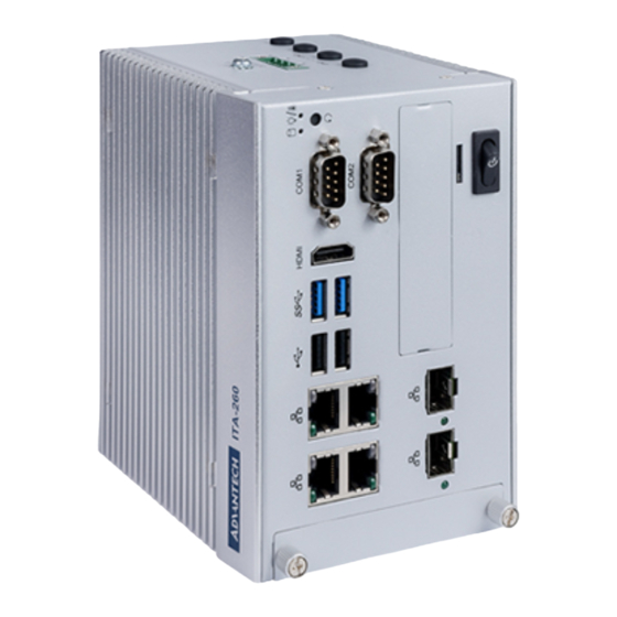
Page 24: I/O Connector
I/O Connector (WxHxD):70x150x120mm with wall mount Front View Rear View (WxHxD):100x150x120mm with wall mount Front View Rear View ITA-260_Series User Manual... -
Page 25: Com Connectors
2.4.1 COM Connectors ITA-260 series provides up to ten D-sub 9-pin connectors for RS-232/422/485. RS-232 RS-422 RS-485 Signal Name Signal Name Signal Name DATA- DATA+ ITA-260_Series User Manual... -
Page 26: Usb Connector
2.4.2 USB Connector ITA-260 provides serial USB3.0 and USB2.0 connector. They can be disabled ins ystem BIOS setup. Signal Name +V5(VCC) USB_data- USB_data+ ITA-260_Series User Manual... -
Page 27: Lan Connector
2.4.3 LAN Connector ITA-260 series is equipped with four LAN controllers. An Intel i210AT/i225 Ethernet controller that complies with IEEE 802.3u 10/100/1000/2500 Base-T is used as the controller chip. The Ethernet port is a standard RJ-45 jack. Additionally, LED indicators are provided on the front of the device to indicate the system’s Link (off/ green/orange) and Active (green) status. -
Page 28: Phoenix Terminal Connector
2.4.4 Phoenix Terminal Connector ITA-260 provides a 4-pin phoenix terminal connectors for power input. Signal Name Positive ITA-260_Series User Manual... -
Page 29: Chapter 3 System Setup
Chapter System Setup This chapter introduces the instal- lation process of ITA-260. -
Page 30: Introduction
Introduction The following procedures will instruct you to install all modules into the ITA-260 sys-tem. 3.1.1 Installing the Motherboard M-sata/MiniPCIe Card The ITA-260 motherboard supports a Mini PCIe or msata expansion card. Please ref er to the installation procedure below. Insert a Mini PCIe/msata card into motherboard MSATA1 slot. -
Page 31: Installing The Ssd Module
3.1.2 Installing the SSD Module ITA-260 reserves the space for installing a 2.5" SSD module. Please refer to the fol-l owing instructions to install the SSD. Place the SSD into 2.5” SSD holder, and lock it with 4 screws. Insert the entire assembled hard disk module into the chassis along the guide r (WxHxD):70x150x120mm with wall mount (WxHxD):100x150x120mm with wall mount Figure 3.2 Installing the SSD Module... -
Page 32: Installing The Top Cover
3.1.3 Installing the Top Cover Please follow the below procedures to install chassis top cover. Insert the top cover on the chassis front panel from the opening point and place it well as shown. (See Figure 3.4) Fix the chassis top cover with two screws. (WxHxD):70x150x120mm with wall mount (WxHxD):100x150x120mm with wall mount Please follow the below procedures to install chassis top heatsink. -
Page 33: Installing The Mounting Bracket
3.1.4 Installing the Mounting Bracket Align the 2 mounting brackets with the screw holes on the chassis side panel, and secure them with screws. Top and bottom installation are both supported. (See Fig3.4) (WxHxD):70x150x120mm with wall moun (WxHxD):100x150x120mm with wall mount Figure 3.4 Installing the mounting Bracket ITA-260_Series User Manual... -
Page 34: Installing The Din Rail Bracket
3.1.5 Installing the DIN RAIL Bracket Align the 2 DINRAIL brackets with the screw holes on the chassis side panel, and secure them with screws. Top and bottom installation are both supported. (See Fig 3.5) (WxHxD):70x150x120mm with wall mount (WxHxD):100x150x120mm with wall mount Figure 3.5 Installing the DIN rail Bracket ITA-260_Series User Manual... -
Page 35: Installing Expansion Module
3.1.6 Installing Expansion Module Please follow the below steps to install AI module. Loosen the five screws and remove heatsink Figure 3.6.1. Insert AI module (e.g MLU 2280) , secure them with screws and attach thermal pad on it according Figure 3.6.2. Daub thermal Grease on the heatsink , and then secure Aluminum block with screws according Figure 3.6.3. - Page 36 Figure 3.6.3 Installing expansion Module Please follow the below steps to install 5G module. Loosen the five screws and remove heatsink Figure 3.6.1. Insert 5G card , secure them with screws and attach thermal pad on it according Figure 3.6.4. Daub thermal Grease on the heatsink , and then secure Aluminum block with screws according Figure 3.6.5.
- Page 37 Figure 3.6.5 Installing expansion Module Please follow the below steps to install AI module. Loosen the five screws and remove heatsink Figure 3.6.1. Insert AI module (e.g VEGA330) , secure them with screws and attach thermal pad on it according Figure 3.6.6. Daub thermal Grease on the heatsink , and then secure Aluminum block with screws according Figure 3.6.7.
- Page 38 Please follow the below steps to install M.2 storage module. Loosen the five screws and remove heatsink Figure 3.6.1. Insert M.2 storage card , secure them with M.3 screws and attach ther mal pad on it according Figure 3.6.8. Select the corresponding slot , daub thermal Grease on the heatsink , a nd then secure Aluminum block with screws according Figure 3.6.9.
- Page 39 ITA-260_Series User Manual...
-
Page 40: Ami Bios
Chapter AMI BIOS This chapter introduces how to configure AMI BIOS. -
Page 41: Introduction
Introduction This chapter introduces how to configure BIOS for ITA-260 series.With the AMI- BIOS Setup program, you can modify BIOS settings and control the special features of your computer. The Setup program uses a number of menus for making changes and turning the special features on or off. -
Page 42: Main Setup
4.2.1 Main Setup When you first enter the BIOS Setup Utility, you will enter the Main setup screen. You can always return to the Main setup screen by selecting the Main tab. There are two Main Setup options. They are described in this section. The Main BIOS Setup screen is shown below. -
Page 43: Advanced Bios Features Setup
4.2.2 Advanced BIOS Features Setup Select the Advanced tab from the ITA-260 setup screen to enter the Advanced BIOS Setup screen. You can select any of the items in the left frame of the screen, such as CPU Configuration, to go to the sub menu for that item. You can display an Advanced BIOS Setup option by highlighting it using the <Arrow>... - Page 44 4.2.2.2 Power & Performance CPU-Power Management Control. 4.2.2.3 PCH-FW Configuration This page shows the version, mode, type, SKU of ME firmware in BIOS. ME State Manageability Features State AMT BIOS Features AMT Configuration Firmware Update Configuration ITA-260_Series User Manual...
- Page 45 4.2.2.4 ACPI Setting Enable Hibernation ACPI Sleep State 4.2.2.5 NCT6126D Supper IO Configuration Serial Port 1/2 Configuration This option configures serial port 1/2 base addresses and IRQ, as well as RS- 232/422/485 mode. Parallel Port Configuration This option configures parallel port base addresses and IRQ ITA-260_Series User Manual...
- Page 46 4.2.2.6 NCT6126D HW Monitor This page shows a part of hardware information which accessed by HW monitor. The user can read the temperature or voltage to analyse the status of the system. Case Open Warning ITA-260_Series User Manual...
- Page 47 4.2.2.7 USB Configuration Legacy USB Support Enable/disable legacy USB support. The default settings is [enabled]. XHCI Hand-off This is a workaround for OS without XHCI hand-off support. The XHCI owner- ship changes should be claimed by XHCI driver. ...
- Page 48 Network Stack Enable/Disable UEFI Network stack. The default setting is [Disabled]. When enable Network stack, the followed picture will be shown: Ipv4 PXE Support Enable/Disable IPV4 PXE support. If disabled, IPV4 PXE boot option will not be created. ...
-
Page 49: Advanced Chipset Settings
4.2.3 Advanced Chipset Settings System Agent (SA) Configuration PCH-IO Configuration 4.2.3.1 System Agent (SA) Configuration Memory Configuration Graphics Configuration ITA-260_Series User Manual... -
Page 50: Security Setup
4.2.3.2 PCH-IO Configuration SATA And RST Configuration PCI Express Configuraion USB Configuration M.2_2 PCIE/USB3.0 Mode Select State After G3 4.2.4 Security Setup Select Security Setup from the ITA-260 Setup main BIOS setup menu. All SecurityS etup options, such as password protection and virus protection are described in thiss ection. -
Page 51: Boot Setup
4.2.5 Boot Setup Setup Prompt Timeout Set the timeout time of setup prompt. Default setting is "1s". Quiet Boot If it's set to "Disabled", the BIOS will display normal POST information. If it's "Enabled", the OEM icon rather than POST information will be shown. ... - Page 52 Discard Changes and Exit Discard changes and exit. Save Changes and Reset Save settings and reset. Discard Changes and Reset Discard changes and reset. Save Changes Save changed settings. Discard Changes Discard changes that have been made. ...
-
Page 53: Driver Installation
Chapter Driver Installation This chapter describes how to Install drivers. -
Page 54: Introduction
Introduction Advantech offers a complete range of Device Driver and software support for Win- dows programming developers. You can apply the Windows Device Drivers to the most popular Windows Programming tools, such as Visual C++, Visual Basic, Bor- land C++ Builder and Borland Delphi. -
Page 55: Appendix A Programming The Watchdog Timer
Appendix Programming the Watchdog Timer... -
Page 56: Watchdog Timer Overview
The ITA-260's watchdog timer can be used to monitor system software operationa nd take corrective action if the software fails to function within the programmedp eriod. This section describes the operation of the watchdog timer and how to pro-g ram it. Watchdog Timer Overview The watchdog timer is built into the super I/O controller NCT6126D. -
Page 57: Program Examples
Program Examples Enable watchdog timer and set 10 sec. as timeout interval Mov dx,A65h ; Select register 65h, watchdog timer I/O port address A00h+ register shifts 65h Mov al,80h ; Set second as counting unit Out dx,al Mov dx,A66h ; Select register 66h, watchdog timer I/O port address A00h+ register shift 66h Mov al,10 ;... - Page 58 No part of this publication may be reproduced in any form or by any means, electronic, photocopying, recording or otherwise, without prior written permis- sion of the publisher. All brand and product names are trademarks or registered trademarks of their respective companies. © Advantech Co., Ltd. 2019...
Need help?
Do you have a question about the ITA-260 Series and is the answer not in the manual?
Questions and answers