
Related Manuals for Advantech ITA-1611 Series


Summary of Contents for Advantech ITA-1611 Series
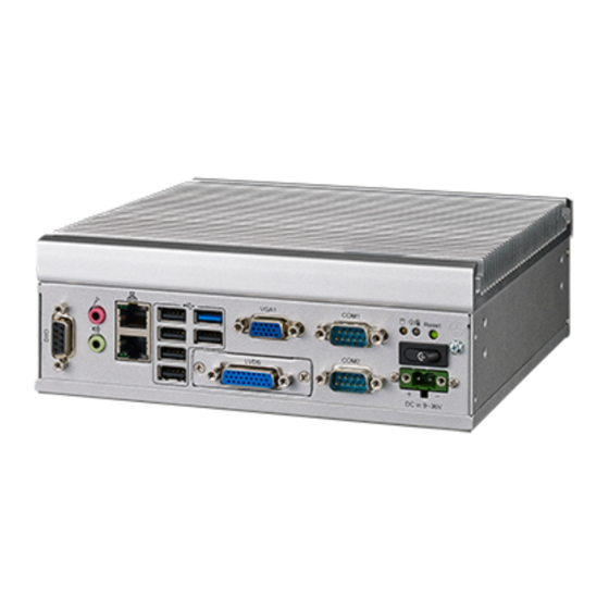
- Page 1 User Manual ITA-1611 Series Fanless Embedded Celeron Dual Core Compact Industrial Computer 電腦...
- Page 2 No part of this manual may be reproduced, copied, translated or transmitted in any form or by any means without the prior written permission of Advantech Co., Ltd. Information provided in this manual is intended to be accurate and reliable. How- ever, Advantech Co., Ltd.
- Page 3 Because of Advantech’s high quality-control standards and rigorous testing, most of our customers never need to use our repair service. If an Advantech product is defec- tive, it will be repaired or replaced at no charge during the warranty period. For out- of-warranty repairs, you will be billed according to the cost of replacement materials, service time and freight.
- Page 4 Advantech has come to be known. Your satisfaction is our primary concern. Here is a guide to Advantech's customer services.
- Page 5 RoHS Claim 設備名稱:電腦 型號 (型式) :ITA-1611( 系列型號參見說明書 ) Equipment name Type designation (Type) 限用物質及其化學符號 Restricted substances and its chemical symbols 多溴聯苯 六價鉻 多溴二苯醚 單元 Unit Polybromina 鎘 Hexavalent Polybrominate 鉛 Lead 汞 Mercury Cadmium chromium d diphenyl (Pb) (Hg) (Cd) biphenyls ethers (PBDE) (PBB)
- Page 6 Warnings, Cautions, and Notes Warning! Warnings indicate conditions, which if not observed, can cause personal injury! Caution! Cautions are included to help you avoid damaging hardware or losing data. e.g. There is a danger of a new battery exploding if it is incorrectly installed. Replace the battery only with the same or equivalent type recom- mended by the manufacturer.
- Page 7 The sound pressure level at the operator's position according to IEC 704-1:1982 is no more than 70 dB (A). DISCLAIMER: This set of instructions is given according to IEC 704-1. Advantech disclaims all responsibility for the accuracy of any statements contained herein.
- Page 8 Safety Precaution - Static Electricity Follow these simple precautions to protect yourself from harm and the products from damage. To avoid electrical shock, always disconnect the power from your PC chassis before you work on it. Don’t touch any components on the CPU card or other cards while the PC is on.
-
Page 9: Table Of Contents
Contents Chapter Overview..........1 Introduction ....................2 Specifications .................... 2 Power Information ..................2 Table 1.1: Power ................. 2 Environmental Specifications ..............3 Table 1.2: Environmental Specifications ........3 Dimension Diagram................... 3 Figure 1.1 Dimension Diagram of ITA-1611 ........ 3 Exploded Diagram..................4 Figure 1.2 Exploded Diagram of ITA-1611 ........ - Page 10 Figure 3.1 Installing the Motherboard CF Card ......18 3.1.2 Installing the Mini PCIe Card ............19 Figure 3.2 Installing the Mini PCIe Card........19 3.1.3 Installing the HDD Module ............20 Figure 3.3 Installing the HDD Module........20 3.1.4 Installing the Top Cover..............
-
Page 11: Chapter 1 Overview
Chapter Overview This chapter provides general Information about the ITA-1611. -
Page 12: Introduction
Introduction The ITA-1611 is a fan-less compact industrial computer chassis with Celeron dual core processor and wide voltage input range, which is specially designed for intelli- gent transportation and e-police applications. This powerful computing platform can stand operation under harsh conditions 24 hours a day, 7 days a week. Specifications ... -
Page 13: Environmental Specifications
Environmental Specifications Table 1.2: Environmental Specifications With industrial HDD: 0 ~ 40°C Operating Temperature With M-SATA card: -25 ~ 60 °C Storage Temperature 85°C º C, Humidity 95% @ 40 non-condensing With M-SATA card: 2 Grms @ 5 ~ 500 Hz, random, 1 hr/axis Vibration With 2.5”... -
Page 14: Exploded Diagram
Exploded Diagram Figure 1.2 Exploded Diagram of ITA-1611 Table 1.3: Part List Heat sink HDD (not included) Power button HDD fixed bracket Power connector Top cover DIO connector Cushion block Wall mounting bracket Front panel Main board PS/2 connector Display plate Replaceable plate Graphic board Printer connector... -
Page 15: Chapter 2 H/W Installation
Chapter H/W Installation This chapter provides H/W Instal- lation about the ITA-1611. -
Page 16: Introduction
Introduction The following sections show the internal jumpers setting and the external connectors pin assignment for application integration. System Status Indicators 2.2.1 System Status LED Indicators The top right LED of the front panel indicates system health and active status. Figure 2.1 Front panel indicators Figure 2.2 Rear panel indicators Refer to below table for a LED definition summary. -
Page 17: Jumpers And Connector
Jumpers and Connector 2.3.1 Jumper Description You may configure the ITA-1611 to match the needs of your application by setting jumpers. A jumper is a metal bridge used to close an electric circuit. It consists of two metal pins and a small metal clip (often protected by a plastic cover) that slides over the pins to connect them. - Page 18 Table 2.1: Jumpers Label Function JCMOS1 Clear CMOS settings AMPL1 L sound channel amplifier switch AMPR1 R sound channel amplifier switch PSON1 AT/ATX mode selection VCCGPIO1 GPIO voltage selection SATA1 SATA data interface 1 SATA2 SATA data interface 2 SATA_PWR1 SATA power interface 1 SATA_PWR2 SATA power interface 2...
- Page 19 Table 2.2: JLVDS1: LVDS Voltage Selection Closed Pins Setting +12V 4/-6 +3.3V (Default) +12V +3.3V Table 2.3: JCOMS1: Clear COMS Selection Closed Pins Setting Normal (+V3.3_SB)* Clear CMOS settings *Default setting Default setting Clear CMOS selection Table 2.4: VCCGPIO1: GPIO Voltage Selection Closed Pins Setting +V3.3_SB...
- Page 20 Table 2.6: AMPL1: L Sound Channel Amplifier Switch Closed Pins Setting 1-2,4-5 L Sound Channel Amplifier Switch ON (Default) 2-3,5-6 L Sound Channel Amplifier Switch OFF (Default) Table 2.7: AMPR1: R Sound Channel Amplifier Switch Closed Pins Setting 1-2,4-5 R Sound Channel Amplifier Switch ON (Default) 2-3,5-6 R Sound Channel Amplifier Switch OFF (Default) ITA-1611 User Manual...
-
Page 21: I/O Connector
I/O Connector Figure 2.4 ITA-1611-00A1E, ITA-1611-10A1E, ITA-1611-20A1E Front I/O Interfaces Figure 2.5 ITA-1611-S0A1E Front I/O Interfaces Figure 2.6 ITA-1611-00A1E Rear I/O Interfaces ITA-1611 User Manual... -
Page 22: Com Connectors
Figure 2.7 ITA-1611-10A1E Rear I/O Interfaces Figure 2.8 ITA-1611-20A1E Rear I/O Interfaces 2.4.1 COM Connectors ITA-1611 series provides up to two D-sub 9-pin connectors for RS-232/422/485. RS-232 RS-422 RS-485 Signal Name Signal Name Signal Name DATA- DATA+ 2.4.2 USB Connector ITA-1611 provides five USB2.0 connectors and a USB3.0 connector. -
Page 23: Vga Connector
Signal Name +V5(VCC) USB_data- USB_data+ 2.4.3 VGA Connector ITA-1611 offers two D-sub 15-pin female connectors. Signal Name Green Blue DDC-DATA H-SYNC V-SYNC DDC-CLK ITA-1611 User Manual... -
Page 24: Dio Connector
2.4.5 Audio in Connector ITA-1611 provides an integrated Mic-in/speaker out audio connector. 2.4.6 LAN Connector ITA-1611 series provide two Intel I211-AT Ethernet controllers, which are fully compli- ant with IEEE 802.3u 10/100/1000 Mbps standard. Signal Name Signal Name A1/B1 MDIO0+... -
Page 25: Phoenix Terminal Connector
A8/B8 MDIO3- MDIO3- A9/B9 LED GREEN- LED GREEN- A10/B10 LED GREEN+ LED GREEN+ A11/B11 1000M LED 1000M LED A12/B12 100m/10M LED 100m/10M LED 2.4.7 Phoenix Terminal Connector ITA-1611 provides a 2-pin phoenix terminal connectors for power input. Signal Name Positive 2.4.8 LVDS Connector ITA-1611-20A1E provides a PS/2 interface for mouse or keyboard connection. -
Page 26: Lpt Connector
2.4.9 LPT Connector ITA-1611-S0A1E provides a LVDS connector which could connect a monitor through cables. Signal Name Signal Name LPT_z_STB# LPT_AFD# LPT_z_PD0 LPT_ERR# LPT_PD1 LPT_INIT# LPT_PD2 LPT_SLIN# LPT_PD3 LPT_PD4 LPT_PD5 LPT_PD6 LPT_PD7 LPT_ACK# LPT_BUSY LPT_PE LPT_SLCT 2.4.10 PS/2 Connector ITA-1611 provides a PS/2 connectors for mouse or keyboard. Signal Name KB_Z_DAT MS_Z_DAT... -
Page 27: Chapter 3 System Setup
Chapter System Setup This chapter introduces the instal- lation process of ITA-1611. -
Page 28: Introduction
Introduction The following procedures will show you how to install all modules into the ITA-1611 system. 3.1.1 Installing the Motherboard M-sata Card ITA-1611 motherboard front panel includes a M-sata card slot for the user to insert a M-sata card directly. Figure 3.1 Installing the Motherboard CF Card ITA-1611 User Manual... -
Page 29: Installing The Mini Pcie Card
3.1.2 Installing the Mini PCIe Card The ITA-1611 motherboard supports a Mini PCIe expansion card. Please refer to the installation procedure below. Carefully insert a Mini PCIe card into motherboard PCIe slot. Lock and fix the Mini PCIe card by a copper pillar. Figure 3.2 Installing the Mini PCIe Card ITA-1611 User Manual... -
Page 30: Installing The Hdd Module
3.1.3 Installing the HDD Module ITA-1611 reserves the space for installing a 2.5" HDD module. Please refer to the fol- lowing instructions to install the HDD. Place the HDD into 2.5” HDD holder, and lock it with 4 screws. The HDD holder has four semi-circles (two bigger and two smaller) on both sides, which are used to place rubber cushions, with the black ones for bigger semi-circles and transparent ones for smaller semi-circles. -
Page 31: Installing The Top Cover
3.1.4 Installing the Top Cover Please follow the below procedures to install chassis top cover. Insert the top cover on the chassis front panel from the opening point and place it well as shown. (See Figure 3.4) Fix the chassis top cover with two screws. Figure 3.4 Installing the Top Cover ITA-1611 User Manual... -
Page 32: Installing The Mounting Bracket
3.1.5 Installing the Mounting Bracket Align the 2 mounting brackets with the screw holes on the chassis side panel, and secure them with screws. Top and bottom installation are both supported. (See Fig 3.5) Figure 3.5 Installing the Mounting Bracket ITA-1611 User Manual... -
Page 33: Chapter 4 Ami Bios
Chapter AMI BIOS This chapter introduces how to configure AMI BIOS. -
Page 34: Introduction
Introduction This chapter introduces how to configure BIOS for ITA-1611 series.With the AMIBIOS Setup program, you can modify BIOS settings and control the special features of your computer. The Setup program uses a number of menus for making changes and turning the special features on or off. -
Page 35: Entering Setup
Entering Setup Turn on the computer to enter POST screen, and BIOS and CPU information will be shown.press <DEL> and you will immediately be allowed to enter Setup. Figure 4.2 Press <DEL> to Enter Setup ITA-1611 User Manual... -
Page 36: Main Setup
4.2.1 Main Setup When you first enter the BIOS Setup Utility, you will enter the Main setup screen. You can always return to the Main setup screen by selecting the Main tab. There are two Main Setup options. They are described in this section. The Main BIOS Setup screen is shown below. -
Page 37: Advanced Bios Features Setup
4.2.2 Advanced BIOS Features Setup Select the Advanced tab from the ITA-1611 setup screen to enter the Advanced BIOS Setup screen. You can select any of the items in the left frame of the screen, such as CPU Configuration, to go to the sub menu for that item. You can display an Advanced BIOS Setup option by highlighting it using the <Arrow>... - Page 38 4.2.2.1 APM Configuration Figure 4.5 ACPI Settings Board Power Mode Show the current startup-up mode. ITA-1611 User Manual...
- Page 39 4.2.2.2 F818264TH Super I/O; F81826SEC Super I/O; F81826THD Super I/O Configuration Serial Port Enable or disable the serial port. Default is “Enabled”. Change Settings Set the mode of serial port devices. Default is the standard serial port mode. ...
- Page 40 4.2.2.3 SH3114 Super IO Configuration Figure 4.6 Super I/O configuration Serial Port1/2/60 This option configures serial port 1/2 base addresses and IRQ, as well as RS- 232/422/485 mode. Parallel Port Configuration This option configures parallel port base addresses and IRQ, as well as RS-232/ 422/485 mode.
- Page 41 Serial Port Enable or disable the serial port. Default is “Enabled”. Serial Port Mode Configure serial port mode. Default is “RS232”. If it’s “RS485”, the auto flow control option will be enabled and the default is “Disabled”. Change settings Change IO address and IRQ settings.
- Page 42 4.2.2.4 Hardware Monitor Figure 4.7 Current System Temperature and Voltage ITA-1611 User Manual...
- Page 43 4.2.2.5 CPU Configuration Figure 4.8 CPU Configuration Socket 0 CPU Information This item allows users to check CPU specifications. Limit CPUID Maximum This item allows users to configure the maximum of CPUID limit value. Execute-Disable Bit This item allows users to enable or disable Execute Disable Bit Feature. The default setting is “Enabled”.
- Page 44 4.2.2.6 IDE Configuration Figure 4.9 IDE configuration Serial-ATA Default setting is “Enabled”, which enables all SATA resources. SATA Test Mode Default setting is “Enabled”, which enables SATA signal testing mode. SATA Speed Support Default setting is “Gen2”. Select “Gen1” or “Gen2” to change SATA transferring rate.
- Page 45 4.2.2.7 USB Configuration Figure 4.10 USB configuration Legacy USB Support Enable legacy USB support. Default setting is “Enabled”. EHCI Hand-Off Enable the operation system without EHCI Hand-off. XHCI Hand-0ff Enable the operation system without XHCI Hand-off. USB Mass Storage Driver Support Default setting is “Enabled”.
-
Page 46: Advanced Chipset Settings
4.2.3 Advanced Chipset Settings 4.2.3.1 North Bridge Chipset Configuration Intel IGD configuration – Integrated Graphics Device Enable internal display device. Default setting is “Enabled”. – IGD Turbo Enable Enable IGD turbo function. Default setting is “Enabled”. – GFX Boost Enable GFX boost function. - Page 47 – DP 1 LVDS Panel Type Configure LVDS display resolution of DP1 interface. – DP 2 LVDS Panel Type Configure LVDS display resolution of DP2 interface. 4.2.3.2 South Bridge Chipset Configuration Azalia HD Audio – LPE Audio Support Configure LPE audio mode. Default setting is “Disabled”. –...
- Page 48 Set the speed of PCIe interface. Default setting is “Auto”. – Extra Bus Reserved Set the amount of reserved extra bus. Default value is “1”. – Reserved Memory Set the range of reserved memory. Default value is “10”. – Reserved Memory Alignment Set the digit of reserved memory alignment.
-
Page 49: Security Setup
4.2.4 Security Setup Figure 4.11 Password Configuration Select Security Setup from the ITA-1611 Setup main BIOS setup menu. All Security Setup options, such as password protection and virus protection are described in this section. To access the sub menu for the following items, select the item and press <Enter>: ... -
Page 50: Boot Setup
4.2.5 Boot Setup Figure 4.12 Boot Configuration Setup Prompt Timeout Set the timeout time of setup prompt. Default setting is “1s”. Quiet Boot If it’s set to “Disabled”, the BIOS will display normal POST information. If it’s “Enabled”, the OEM icon rather than POST information will be shown. Fast Boot ... -
Page 51: Save And Exit
4.2.6 Save and Exit Save Changes and Exit Save settings and exit. Discard Changes and Exit Discard changes and exit. Save Changes and Reset Save settings and reset. Discard Changes and Reset Discard changes and reset. ... - Page 52 ITA-1611 User Manual...
-
Page 53: Chapter 5 Driver Installation
Chapter Driver Installation This chapter describes how to Install drivers. -
Page 54: Introduction
Introduction Advantech offers a complete range of Device Driver and software support for Win- dows programming developers. You can apply the Windows Device Drivers to the most popular Windows Programming tools, such as Visual C++, Visual Basic, Bor- land C++ Builder and Borland Delphi. -
Page 55: Chipset Windows Driver Setup
5.2.2 VGA Windows Driver Setup Insert the driver CD into your system’s CD-ROM drive. You can see the driver folder of ITA-1611 series. Navigate to the “01_VGA” folder and click “Setup.exe” to com- plete driver installation. ITA-1611 User Manual... -
Page 56: Lan Windows Driver Setup
5.2.3 LAN Windows Driver Setup Insert the driver CD into your system’s CD-ROM drive. You can see the driver folder of ITA-1611 series. Navigate to the “02_LAN” folder and click “Autorun.exe” to com- plete driver installation. 5.2.4 AUDIO Windows Driver Setup Insert the driver CD into your system’s CD-ROM drive. -
Page 57: Chapter 6 Gpio Programming Guide
Chapter GPIO Programming Guide This chapter introduces GPIO pro- gramming guide. - Page 58 Please carefully read and refer to the below examples and source codes in bold. Please download NXP Semiconductors PAC9554 spec to start programming. Digital IO definition of ITA-1610: Configuration sequence: ITA-1610’s GPIO is realized by a PCA9554 GPIO IC on ICH SMBUS. As a result, configuration and access to GPIO IC should be done via accessing IO Space of ICH SMBUS controller.
- Page 59 PCA9554 register: In write transmission, command byte is the first byte after the address byte. It is used as a pointer to decide which register to read/write. PCA9554 has four registers to control GPIO. PCA9554 register 0: This register is read only. It shows input logic level of the pin, and has nothing to do with the input or output direction defined by Register 3.
- Page 60 PCA9554 register 1: This register reflects outgoing logic level of pins defined as outputs by Register 3. The Bit value in this register will not respond to input pin. When reading this register, value of flip-flop which controls output will be returned, while the actual pin’s physical signal value will not be returned.
- Page 61 PCA9554 register 3: This register configures directions of I/O pins. If value of a certain bit of this register is set, pin of corresponding port will be defined as inputs with high impedance output driver. If the value is cleared, then the port will be defined as outputs. When reset, ini- tial definition of I/O will be inputs with weak pull-up to VDD.
-
Page 62: 6.1 Function Call Reference
6.1 Function Call Reference ICH SMBUS Access code ?The following codes simulate BIOS visiting SMBUS. Borland C++ 3.1 compiles OK. This has be tested under DOS, nut not other OS? #define SMBUS_PORT 0x400//SMB_BASE?0x400 typedefunsigned char BYTE; //////////////////////////////////////////////////////////////////////////////////////////////////// BYTEsmbus_read_byte(BYTE addr, BYTE offset) //Read value of SMBUS Register byte. - Page 63 chk_smbus_ready();//Determine if SMBUS is ready outportb(SMBUS_PORT + 3, offset);//write register offset to SMB_BASE + 3 moredelay();//long time delay moredelay();//long time delay outportb(SMBUS_PORT + 5, value);//Write data value to SMB_BASE + 5 moredelay();//long time delay moredelay();//long time delay outportb(SMBUS_PORT + 2, 0x48);//Write SMBUS command to SMB_BASE + 2, 0x48 means starting Byte data transmission moredelay();//long time delay...
- Page 64 if (data & 0x04) //If bit 2 is set to 1 (this means SMBUS error), then error has occurred in SMBUS. This rarely happens result = 1;//SMBUS error break; returnresult; //////////////////////////////////////////////////////////////////////////////////////////////////// BYTEcheck_data(WORD addr) int i; BYTE data; for(i = 0; i <= 6; i++) data = inportb(addr);...
- Page 65 (Take GPIO 00 and GPIO 07 in Chapter 2 for example) GPIO 00 output High: data = smbus_read_byte(0x40, 0x03);//Read slave 0x40 register 3 byte data &= 0xfe;//Set bit 0 to 0 smbus_write_byte(0x40, 0x03, data)//Write back, GPIO 00 is set to Output data = smbus_read_byte(0x40, 0x01)//Read slave 0x40 register 1 data |=...
- Page 66 ITA-1611 User Manual...
-
Page 67: Appendix A Programming The Watchdog Timer
Appendix Programming the Watchdog Timer... -
Page 68: Watchdog Timer Overview
The ITA-1611's watchdog timer can be used to monitor system software operation and take corrective action if the software fails to function within the programmed period. This section describes the operation of the watchdog timer and how to pro- gram it. Watchdog Timer Overview The watchdog timer is built into the super I/O controller SMSC SCH3114. -
Page 69: Program Examples
Program Examples Enable watchdog timer and set 10 sec. as timeout interval Mov dx,A65h ; Select register 65h, watchdog timer I/O port address A00h+ register shifts 65h Mov al,80h ; Set second as counting unit Out dx,al Mov dx,A66h ; Select register 66h, watchdog timer I/O port address A00h+ register shift 66h Mov al,10 ;... - Page 70 No part of this publication may be reproduced in any form or by any means, electronic, photocopying, recording or otherwise, without prior written permis- sion of the publisher. All brand and product names are trademarks or registered trademarks of their respective companies. © Advantech Co., Ltd. 2016...
Need help?
Do you have a question about the ITA-1611 Series and is the answer not in the manual?
Questions and answers