Advertisement
Maintenance Manual
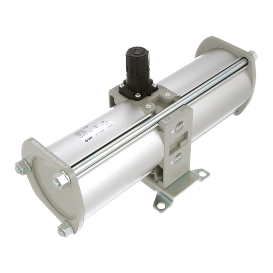
Booster Regulator
1. Foreword・・・・・・・・・・・・・・・・・・・・・・・・・・・・・・・・・・・・P.1
2. Maintenance of cylinder and body・・・・・・・・・・・・・・
3. Maintenance of governor・・・・・・・・・・・・・・・・・・・・・・
4. Replacement parts list・・・・・・・・・・・・・・・・・・・・・・・・
VBA40A
−Contents−
VBA-MM-L004-B
P.2
P.4
P.5
Advertisement
Table of Contents

Related Manuals for SMC Networks VBA40A


Summary of Contents for SMC Networks VBA40A
- Page 1 VBA-MM-L004-B Maintenance Manual Booster Regulator VBA40A −Contents− 1. Foreword・・・・・・・・・・・・・・・・・・・・・・・・・・・・・・・・・・・・P.1 2. Maintenance of cylinder and body・・・・・・・・・・・・・・ 3. Maintenance of governor・・・・・・・・・・・・・・・・・・・・・・ 4. Replacement parts list・・・・・・・・・・・・・・・・・・・・・・・・...
- Page 2 1. Foreword When the booster regulator is disassembled and reassembled for maintenance, read and follow this manual. Maintenance period depends on air quality and operating conditions, but when either of following situations are seen on the booster regulator, the booster regulator should be considered to come close to its life end and given maintenance at earlier period.
- Page 3 2. Maintenance of cylinder and body 2.1 Maintenance of cylinder ◆Necessary items◆ Socket wrench, Nominal 19 (2pcs) Looseness preventive adhesive (Loctite 243, etc.) ◆Disassembly procedure◆ 1) Check air pressure is exhausted from the IN and OUT sides. 2) Loosen the hexagon nuts (12) and spring washers (11) with the socket wrench, and remove three tie rods (10).
- Page 4 2.2 Maintenance of body ◆Necessary tools◆ Phillips driver Pincettes Turbine oil (Turbine oil 32 class 2, Exxon Mobile or like that) ◆Disassembly◆ 1) Remove six cross recessed flat head screws (7) at the right and left sides with the Phillips driver. 2) Take off the side plates (6) at the right and left.
- Page 5 3. Maintenance of governor ◆Necessary tools◆ Phillips driver Radio pliers ◆Disassembly◆ 1) Check air pressure is exhausted from the IN and OUT sides. 2) Rotate the handle counterclockwise back to the end (one direction). 3) Remove four cross recessed round head screws (7) with the Phillips driver. 4) Remove the bonnet assemblies (6) and (8), pressure adjusting screw (5), pressure adjusting spring (4) and diaphragm assembly (3).
- Page 6 Dwg. no. Piston seal Fig. 1 Rod seal Fig. 2 O-ring (gasket) Fig. 1 Booster regulator Governor assembly Fig. 3 KT-VBA40A-1 maintenance Check valve Fig. 2 (2),(3) parts set Cross recessed flat head screw Fig. 2 (mounting screw) Grease package -...
Need help?
Do you have a question about the VBA40A and is the answer not in the manual?
Questions and answers