Advertisement
Quick Links
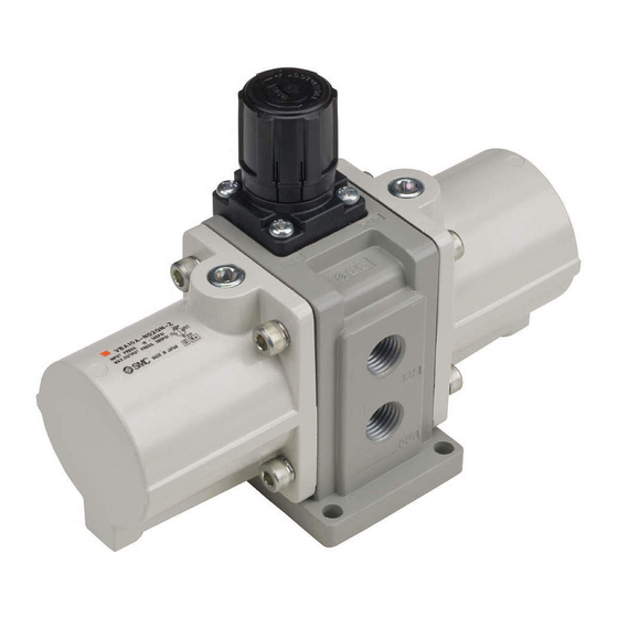
Maintenance Manual
Booster Regulator
1. Foreword・・・・・・・・・・・・・・・・・・・・・・・・・・・・・・・・・・・・P.1
2. Maintenance of cylinder and body・・・・・・・・・・・・・・
3. Maintenance of governor・・・・・・・・・・・・・・・・・・・・・・
4. Replacement parts list・・・・・・・・・・・・・・・・・・・・・・・・
VBA10A
-Contents-
VBA-MM-N010-E
P.2
P.4
P.5
Advertisement

Related Manuals for SMC Networks VBA10A


Summary of Contents for SMC Networks VBA10A
- Page 1 VBA-MM-N010-E Maintenance Manual Booster Regulator VBA10A -Contents- 1. Foreword・・・・・・・・・・・・・・・・・・・・・・・・・・・・・・・・・・・・P.1 2. Maintenance of cylinder and body・・・・・・・・・・・・・・ 3. Maintenance of governor・・・・・・・・・・・・・・・・・・・・・・ 4. Replacement parts list・・・・・・・・・・・・・・・・・・・・・・・・...
- Page 2 1. Foreword When the booster regulator is disassembled and reassembled for maintenance, read and follow this manual. The maintenance period depends on the air quality and operating conditions, but when either of the following situations occurs, the booster regulator should be considered to be reaching the end of its life, and maintenance should be performed sooner.
- Page 3 2. Maintenance of cylinder and body 2.1 Maintenance of cylinder ◆ ◆ ◆ ◆ Necessary tools◆ ◆ ◆ ◆ Socket wrench, Nominal 10mm (2pcs) Hexagon wrench, Nominal 5mm Looseness preventive adhesive (Loctite 263, etc.) Grease package (Multi-purpose2, etc.) ◆ ◆ ◆ ◆ Disassembly procedure◆ ◆ ◆ ◆ 1) Check air pressure is exhausted from the IN and OUT sides.
- Page 4 2.2 Maintenance of body ◆ ◆ ◆ ◆ Necessary tools◆ ◆ ◆ ◆ Flat blade screwdriver Pair of tweezers Turbine oil (Turbine oil 32 class 2, Exxon Mobile or similar) Grease package (Multi-Purpose 2, etc) ◆ ◆ ◆ ◆ Disassembly◆ ◆ ◆ ◆ 1) Take off the side plates (2) on the right and left.
- Page 5 3. Maintenance of governor ◆ ◆ ◆ ◆ Necessary tools◆ ◆ ◆ ◆ Phillips screwdriver Pair of needle nose pliers ◆ ◆ ◆ ◆ Disassembly◆ ◆ ◆ ◆ 1) Check air pressure is exhausted from the IN and OUT sides. 2) Rotate the handle counterclockwise back to the end (in the negative direction).
- Page 6 Qty. Piston seal Fig. 1 Rod seal Fig. 2 (14) Governor gasket Fig. 1 Booster regulator Valve assembly Fig. 3 KT-VBA10A-1 maintenance Governor chamber assembly Fig. 3 parts set Check valve Fig. 2 Valve spring Fig. 3 - - Grease package Switch valve assembly Fig.
Need help?
Do you have a question about the VBA10A and is the answer not in the manual?
Questions and answers