Advertisement
Safety Instructions
These safety instructions are intended to prevent hazardous situations and/or equipment damage. These instructions indicate the level of potential hazard with the labels of "Caution," "Warning" or "Danger." They are all important notes for safety and must be followed in addition to International Standards (ISO/IEC) *1), and other safety regulations.
*1) ISO 4414: Pneumatic fluid power - General rules relating to systems.
ISO 4413: Hydraulic fluid power - General rules relating to systems.
IEC 60204-1: Safety of machinery - Electrical equipment of machines.
(Part 1: General requirements)
ISO 10218-1: Manipulating industrial robots -Safety. etc.
- Refer to product catalogue, Operation Manual and Handling Precautions for SMC Products for additional information.
- Keep this manual in a safe place for future reference.
 | Indicates a hazard with a low level of risk which, if not avoided, could result in minor or moderate injury. |
 | Indicates a hazard with a medium level of risk which, if not avoided, could result in death or serious injury. |
 | Indicates a hazard with a high level of risk which, if not avoided, will result in death or serious injury. |
- Always ensure compliance with relevant safety laws and standards.
- All work must be carried out in a safe manner by a qualified person in compliance with applicable national regulations.
- This product is class A equipment intended for use in an industrial environment. There may be potential difficulties in ensuring electromagnetic compatibility in other environments due to conducted or radiated disturbances.
- Special products (-****) might have specifications different from those shown in the Specifications section. Contact SMC for specific drawings.
Specifications
| Model | D-B53 | D-B54 | D-B64 | D-B59W | ||||
| Wiring style | 2 wire | |||||||
| Application | Relay, PLC | |||||||
| Maximum Load voltage | 24 VDC | 24 VDC | 100 VAC | 200 VAC | 24 V AC/DC | 100 VAC | 200 VAC | 24 VDC |
| Maximum Load current (or range) | 5 to 50 mA | 5 to 50 mA | 5 to 25 mA | 5 to 12.5 mA | 50 mA | 25 mA | 12.5 mA | 5 to 40 mA |
| Contact protection | None | Built in | ||||||
| Max. internal voltage drop | 2.4 V | 2.4 V (< 20 mA) 3.5 V (< 50 mA) | - | 4 V | ||||
| Internal resistance | - | 25 Ω or less | - | |||||
| Operating time | 1.2 ms | |||||||
| Indicator lamp | Red LED is ON when switch is ON | - | Operating: Red Optimum: Green | |||||
| Impact proof | 300 m/s2 | |||||||
| Insulation resistance | 50 MΩ or more at 500 VDC mega | |||||||
| Proof voltage | (between case and lead wire)1500 VAC for 1 minute | |||||||
| Ambient | -10 to 60°C | |||||||
| temperature Enclosure Protection | IP67 to IEC 60529 (JISC 0920) | |||||||
| Lead wire | φ4 oilproof heavy duty vinyl cable, 2 cores: 0.3 mm2 | |||||||
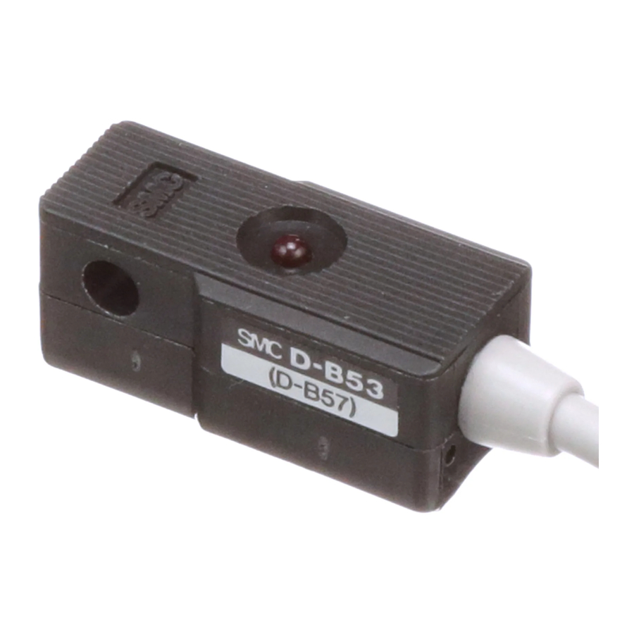
Names and function of parts

D-B53 / D-B54 / D-B64

D-B59W
Note: There is no indicator lamp in model "D-B64"
Installation
- Do not install the product unless the safety instructions have been read and understood.
Design and Selection
- Confirm the specifications. Read the specifications carefully and use the product correctly. The product may be damaged or malfunction if it is used outside of the specification range.
- Take precautions when multiple actuators are used close together. When multiple auto switch actuators are used in close proximity, magnetic field interference may cause the switches to malfunction. Maintain a minimum actuator separation of 40 mm.
- Pay attention to the length of time that a switch is ON at an intermediate stroke position. When an auto switch is placed at an intermediate position of the stroke and a load is driven at the time the piston passes, the auto switch will operate, but if the speed is too great the operating time will be short and the load may not operate correctly. The maximum detectable piston speed is:

- Keep wiring as short as possible As the wire length to a load is increased, the inrush current at switch ON becomes greater, which may shorten the product life (the switch will stay constantly ON). Use a contact protection box (CD-P11/CD-P12) when the wire length is 5 m or longer.
- Pay attention to the internal voltage drop of the switch.
- Switches with an indicator LED
- If auto switches are connected in series, take note that there will be a large volt drop because of internal resistance in the LED's (refer to internal voltage drop in the auto switch specifications). [The voltage drop will be "n" times larger when "n" auto switches are connected]. Even though an auto switch operates normally, the load may not operate.
- In the same way, when operating below a specified voltage, although the auto switch may operate normally, the load may not operate. Therefore, the formula below should be satisfied after confirming the minimum operating voltage of the load. Supply Internal volt drop -- Minimum operating voltage of switch > voltage of load
- Switches with an indicator LED

- If the internal resistance of an LED causes a problem, select a switch without an indicator light (model D-B64).
- Do not use a load that generates a surge voltage. If driving a load such as a relay that generates a surge voltage, use a contact protection box.
- Caution for use in an interlock circuit When an auto switch is used for an interlock signal requiring high reliability, devise a double interlock system by providing a mechanical protection function, or by using another switch (sensor) together with the auto switch.
- Perform periodical maintenance and confirm proper operation. Ensure sufficient clearance for maintenance activities. When designing an application, be sure to allow sufficient clearance for maintenance and inspections.
Mounting and Adjustment
- Do not drop or bump the product. Do not drop, bump or apply excessive impact (300 m/s 2 or more) while handling. Although the body of the switch may not appear damaged, the inside of the switch may be damaged and cause a malfunction.
- Do not carry an actuator by the auto switch lead wires. This may not only cause broken lead wires, but it may cause internal elements of the switch to be damaged by the stress.
- Mount switches using the correct tightening torque. If a switch is tightened beyond the tightening torque range, the mounting screw, mounting bracket or switch may be damaged. On the other hand, tightening below the tightening torque range may allow the switch to slip out of position.
- Mount a switch at the centre of the operating range. Adjust the auto switch mounting position so that the piston stops at the centre of the operating range (the range in which the switch is ON). The auto switch Red LED will turn ON. For the 2 colour type auto switch (D-B59W) the Green LED turns ON to indicate the optimum position. The mounting position shown in the catalogue indicates the optimum position at the end of stroke. If mounted at the end of the operating range (around the borderline of ON and OFF) operation may be unstable.
- The auto switch ON and OFF position operates with a hysteresis. If the hysteresis causes a problem, please consult with SMC.


Mounting using a mounting bracket
Each actuator has a specified mounting bracket type.
Mounting depends on the actuator type and tube I.D. Please refer to the actuator catalogue.
When an auto switch is mounted for the first time, ensure that the actuator is the type with a built-in magnet, and prepare a mounting bracket corresponding to the actuator.
- Mounting procedure
- Place a mounting band on to the cylinder tube and set it at the required auto switch mounting position.


- Put the mounting part of the auto switch between the band mounting holes, then adjust the position of the switch mounting holes to those of the mounting band.
- Lightly thread the auto switch mounting screw through the mounting hole into the threaded part of the band fitting.
- After sliding the whole body to the detecting position, tighten the mounting screw to secure the auto switch while properly contacting the auto switch bottom part to the cylinder tube. Tightening torque of the M4 screw should be 1.0 to 1.2 N•m.
- Modification of the detecting position should be made following step number (3).
Note 1: Tighten the screw according to the specified torque when mounting the auto switch.
Note 2: Set the auto switch mounting band perpendicular to cylinder tube.

Wiring
- Avoid repeatedly bending or stressing lead wires. Broken lead wires can result from wiring layouts which repeatedly apply bending stress or stretching force to the lead wires.
- Be sure to connect the load before power is applied. If the power is turned ON when an auto switch is not connected to a load, the switch will be instantly damaged due to excess current.
- Confirm proper insulation of wiring. Check that there is no faulty wiring insulation (contact with other circuits, ground fault, improper insulation between terminals, etc.) Damage may occur due to excess current flow into a switch.
- Do not route wiring with power lines or high voltage lines. Avoid parallel wiring or wiring in the same conduit with these lines. Control circuits containing auto switches may malfunction due to noise.
- Do not allow short circuit of loads. If power is turned ON with a load in a short circuit condition, the switch will be instantly damaged due to excess current flow.
- Avoid incorrect wiring An auto switch with indicator light has polarity. The brown [red] lead wire is (+), and the blue [black] lead wire is (–). If connections are reversed, the switch will operate, however, the LED will not light up. Also note that a current greater than that specified will damage the LED and it will no longer operate.
Wiring diagram

D-B53

D-B54

D-B64

D-B59W
Environment
- Do not use in an environment where oil, corrosive gases, chemicals, salt water or steam are present.
- Do not install in a location subject to vibration or impact in excess of the product specifications.
- Do not mount in a location exposed to radiant heat that would result in temperatures in excess of the product specification.
- Do not use in an area where a magnetic field is generated. Auto switches can malfunction or magnets inside actuators can become demagnetized.
- Do not use in an environment where the auto switch will be continually exposed to water.
- Do not use in an environment with temperature cycles.
- Avoid accumulation of iron waste or close contact with magnetic substances. A large amount of accumulated iron waste such as machining chips or spatter may cause the auto switch to malfunction.
How to Order
Refer to the catalogue or operation manual on the SMC website (URL: https// www.smcworld.com ) for How to order information.
Outline dimensions
Refer to the catalogue or operation manual on the SMC website (URL: https// www.smcworld.com ) for outline dimensions.
Maintenance
General Maintenance
- Not following proper maintenance procedures could cause the product to malfunction and lead to equipment damage.
- If handled improperly, compressed air can be dangerous.
- Maintenance of pneumatic systems should be performed only by qualified personnel.
- Before performing maintenance, turn off the power supply and be sure to cut off the supply pressure. Confirm that the air is released to atmosphere.
- After installation and maintenance, apply operating pressure and power to the equipment and perform appropriate functional and leakage tests to make sure the equipment is installed correctly.
- If any electrical connections are disturbed during maintenance, ensure they are reconnected correctly and safety checks are carried out as required to ensure continued compliance with applicable national regulations.
- Do not make any modification to the product.
- Do not disassemble the product, unless required by installation or maintenance instructions.
- Perform the following maintenance periodically in order to prevent
- Securely tighten switch mounting screws. If screws become loose or the mounting position is dislocated, re-tighten them after readjusting the mounting position.
- Confirm that there is no damage to lead wires. To prevent faulty insulation, replace switches or repair lead wires, etc., if damage is discovered.
Troubleshooting
When detection failure occurs check the switch according to the chart

- Auto switch failure
- Replace the actuator. Detectable magnetic field inadequate (or no magnet).
- Correct the wiring, replace the load or replace the auto switch after correcting the wiring.
- After checking the operating environment, replace the auto switch.
- Replace the auto switch after correcting the wiring.
URL:
https// www.smcworld.com (Global)
https// www.smc.eu (Europe)
SMC Corporation, Akihabara UDX15F, 4-14-1, Sotokanda, Chiyoda-ku, Tokyo 101 0021 Specifications are subject to change without prior notice from the manufacturer.

Documents / Resources
References
Download manual
Here you can download full pdf version of manual, it may contain additional safety instructions, warranty information, FCC rules, etc.
Download SMC D-B53, D-B54, D-B64, D-B59W Series - Reed Auto Switch Manual
Advertisement


Need help?
Do you have a question about the D-B53 Series and is the answer not in the manual?
Questions and answers