SST Automation GT200-HT-MT User Manual
Hart / modbus tcp gateway
Hide thumbs
Also See for GT200-HT-MT:
- User manual (64 pages) ,
- User manual (46 pages) ,
- User manual (45 pages)

Related Manuals for SST Automation GT200-HT-MT


Summary of Contents for SST Automation GT200-HT-MT
- Page 1 HART / Modbus TCP Gateway GT200-HT-MT User Manual V 1.2 Rev G SST Automation Email: support@sstautomation.com www.SSTAutomation.com...
- Page 2 The product has many applications. The users must make sure that all operations and results are in accordance with the safety of relevant fields, and the safety includes laws, rules, codes and standards. Copyright Copyright © 2022 by SST Automation. All rights reserved. Trademark is the registered trade mark of SST Automation.
-
Page 3: Table Of Contents
2.4 Interface ................................6 2.4.1 Power Interface ........................... 6 2.4.2 Ethernet Interface ..........................7 2.4.3 HART Interface ........................... 7 2.5 Topology of GT200-HT-MT and HART Instruments ..................8 2.5.1 Point-to-Point Wiring .......................... 9 2.5.2 Multi-Drop Wiring ..........................11 3 Hardware Installation .............................. 12 3.1 Mechanical Dimensions .......................... - Page 4 5.2.5 Upload Configuration ........................57 5.2.6 Download Configuration ........................59 5.2.7 Memory Data Display ........................59 5.2.8 Diagnose ............................61 5.2.9 Conversion Tools ..........................65 6 Working Principle ..............................66 6.1 Address Table ............................... 66 6.2 Flowchart of Executing One HART Command ...................69 6.3 Trigger Command ............................69 www.SSTAutomation.com...
-
Page 5: Product Overview
1 Product Overview 1.1 Product Function GT200-HT-MT is a gateway that can provide a seamless connection between HART instruments and a Modbus TCP network. It can connect HART slave devices to a Modbus TCP network and realize bi-directional data exchange easily. The HART interface can be configured as a primary master or a secondary master. It acts as a server at the Modbus TCP side. -
Page 6: Related Products
In multi-drop mode, up to 13 HART instruments can be connected with an internal series resistor (270Ohm/2W), and up to 15 HART instruments with an external series resistor (250Ohm/3W). [4] Supports all commands of the HART 6 protocol. [5] Each HART command can be configured to different outputting mode: change-of-state output, polling output, initialization output or disable output. -
Page 7: Revision History
1.5 Revision History Revision Date Chapter Description V1.2, Rev A 02/11/2017 Add description for chapter 4.2.7, 4.2.8. V1.2, Rev B 11/16/2020 V1.2, Rev C 12/25/2020 Chapter 5 V1.2, Rev D 7/23/2021 Chapter 4, 6 New chapter 4.2. Address table revised. V1.2, Rev E 07/01/2022 Chapter 5.2.2.3... -
Page 8: Hardware Descriptions
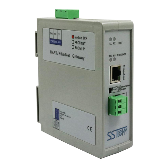
2 Hardware Descriptions 2.1 Product Appearance HART Indicators Power Interface Ethernet Indicators Ethernet interface Resistor Switch HART Interface DIP Switch Note: This picture is for reference only. The product appearance is subject to the actual product. www.SSTAutomation.com... -
Page 9: Led Indicators
Connection is OFF (For 3 seconds) 2.3 Configuration Switch/Button 2.3.1 Configuration Switch The configuration DIP switches are located at the bottom of the GT200-HT-MT and are used to set the operating mode of the device. On 1 2 Mode (Bit 1) -
Page 10: Resistor Switch
2.3.2 Resistor Switch The GT200-HT-MT has an internal series (270Ohm/2W) resistor required for the HART channel. This supports up to 13 HART instruments to be connected. When the power of the series resistor is more than 2W, you must use an external series resistor (250Ohm/3W), which allows the gateway to support up to 15 HART instruments to be connected. -
Page 11: Ethernet Interface
2.4.2 Ethernet Interface The Ethernet interface uses RJ45 interface, follows the IEEE802.3u 100BASE-T standard, 10/100M adaptive routing. its pin (standard Ethernet signal) is defined as below: Description TXD+, Transmit Data+, Output TXD-, Transmit Data-, Output RXD+, Receive Data+, Input Bi-directional Data+ Bi-directional Data- RXD-, Receive Data-, Input Bi-directional Data+... -
Page 12: Topology Of Gt200-Ht-Mt And Hart Instruments
2.5 Topology of GT200-HT-MT and HART Instruments Notes: It is recommended to use a separate power supply for the HART instruments and the GT200-HT-MT to ensure stable communication. To improve the communication efficiency of the field bus, it is recommended not to configure empty nodes or unnecessary commands in the SST-HE-CFG software. -
Page 13: Point-To-Point Wiring
2.5.1 Point-to-Point Wiring The following are the topologies for two wire and four wire point-to-point wiring. www.SSTAutomation.com... - Page 14 www.SSTAutomation.com...
-
Page 15: Multi-Drop Wiring
2.5.2 Multi-Drop Wiring The following are the topologies for two wire and four wire multi-drop wiring. Two wire: Four wire: www.SSTAutomation.com... -
Page 16: Hardware Installation
3 Hardware Installation 3.1 Mechanical Dimensions Size: 1.6 in (width) *5.0 in (height) *4.4 in (depth) www.SSTAutomation.com... -
Page 17: Mounting Method
3.2 Mounting Method Using 1.38 in (35mm) DIN RAIL. Install the gateway Uninstall the gateway 1. Use a screwdriver to pass through the DIN RAIL bar, pull down and hold. 2. Pull out the gateway. 3. Lift up the gateway. ③... -
Page 18: Quick Start Guide
4.1 Start 4.1.1 Connection Make sure the GT200-HT-MT is in the appropriate operating mode that allows for configuration. It is recommended to set the gateway to configuration mode (configuration switches Bit 1 ON and Bit 2 OFF) then the IP of the gateway will be fixed at 192.168.0.10. - Page 19 You will see the factory default configuration settings are shown below: Note: There are already two commands and an IP Address preset into the device. You can edit these parameters for your needs. Command ID1 is pre-configured to read the PV. (For your reference, the default configuration for this command is shown below.) Command ID3 is pre-configured to read the PV, SV, TV, and QV.
-
Page 20: Configuration
4.1.3 Configuration Open the SST-HE-CFG software installed on your computer. Click “Fieldbus” in the “Mode” item on the right and choose “Modbus TCP”. Select “Ethernet Config” in “Config” menu. www.SSTAutomation.com... - Page 21 Click “OK”. Select the gateway and sign in. Select the “Fieldbus” on the left and configure the parameters as below: Click the HART channel on the left and configure the parameters as below: www.SSTAutomation.com...
- Page 22 Right click the channel, select “Add Node”. Right click on “Node(0)” and select “Add Command” and add Command ID1 box (double click on “Command ID1” or select “Command ID1” and click “»”). Click OK. www.SSTAutomation.com...
- Page 23 Click “Command ID1” and configure the parameters as below: 10. Click the AutoMap icon 11. Click the Download icon www.SSTAutomation.com...
-
Page 24: Communication With Modbus Tcp Client
4.2 Communication with Modbus TCP Client The GT200-HT-MT is able to connect HART instruments to Modbus TCP network as a Modbus TCP server. The following example shows how the GT200-HT-MT communicates with Modbus Poll (a Modbus simulator software). Configure the GT200-HT-MT with some HART nodes and commands. In this example, the GT200-HT-MT is configured with HART commands 1, 3 and 6 for one node. - Page 25 (2) Command 3: Advanced configuration mode. Double click any values to filter them out. Update the configuration to read only bytes No.5-8, 10-13 and 15-18. The others can be filtered out. The remaining bytes are the secondary, tertiary and quaternary variables. (3) Command 6: 2-byte request and 2-byte response.
- Page 26 After mapping the data, check the buffer address in Conflict Detection window. The request data bytes of command 6 are stored in 3000~3001 bytes. The response data bytes of command 1 are stored in 0~6 bytes, command 3 in 7~18bytes and command 6 in 19~22 bytes. According to the address table in chapter 6.1, Modbus TCP client should read/write the 4x1501 holding...
- Page 27 This example uses Modbus Poll on the computer to simulate the Modbus TCP client. Set the correct server IP and read/write parameters. www.SSTAutomation.com...
- Page 28 You can use the advanced function Memory Data Display (see chapter 5.2.7) or Diagnose (see chapter 5.2.8) to monitor the HART communication. (1) Memory Data Display (2) Diagnose: According to the specifications of HART command, you can convert the hexadecimal data to float number.
-
Page 29: Troubleshooting Multiple Hart Devices
4.3 Troubleshooting Multiple HART Devices The GT200-HT-MT can receive data from up to 15 HART devices connected on the same bus. The following example shows how to configure the GT200-HT-MT in multi-drop mode to receive data from multiple HART nodes. - Page 30 Click "OK". Select the gateway and sign in. Select the "Fieldbus" on the left and configure the parameters as below: www.SSTAutomation.com...
- Page 31 Click the HART channel on the left, configure the parameters as below: Right click the channel, select “Add Node”. Right click on “Node(0)” and select “Add Command” and add Command ID3 box (double click on “Command ID3” or select “Command ID3” and click “»”). Click OK. www.SSTAutomation.com...
- Page 32 10. Click “Command ID3” and configure the parameters as below: 11. Click the AutoMap icon 12. Click the Download icon www.SSTAutomation.com...
- Page 33 13. Check the LED indicators to verify the device status. If both TX and RX lights are flashing, then the device is configured to slave address 0. If the RX light is not flashing, then change Network Mode to Multi-drop and proceed to step 14.
- Page 34 16. Right click on “Node(1)” and select “Add Command” and add Command ID3 box (double click on “Command ID3” or select “Command ID3” and click “»”). Click OK. 17. Click “Command ID3” and configure the parameters as below: www.SSTAutomation.com...
- Page 35 18. Right click on “Node(1)” and select “Copy Node”. 19. Right click on “Node (1)” and select “Paste Node”. Repeat this step until there are 15 nodes. www.SSTAutomation.com...
- Page 36 20. Click the AutoMap icon www.SSTAutomation.com...
- Page 37 21. Click the Download icon 22. Check the LED indicators to verify the device status. If both TX and RX lights are flashing, then the device is configured in multi-mode and has a slave address anywhere between 1-15. To find the exact slave address, remove nodes and repeat steps 20-22.
-
Page 38: Changing Hart Slave Addresses
4.3.2 Changing HART Slave Addresses The SST-HE-CFG software has a built-in Debug mode with a Memory Display function that can be used to read and write data to HART devices. This functionality can be used to change the HART slave address of the device with the following steps: Right click on “Node”... - Page 39 Click the AutoMap icon Click the download icon www.SSTAutomation.com...
- Page 40 Click the Mode Switch icon to switch into Debug mode Click the Diagnose icon www.SSTAutomation.com...
- Page 41 Click “Stop” in the Output Data box, update memory address 3000 with the desired HART slave address, and click the “Send” button. The following example shows how to change from slave address 0 to address 2. www.SSTAutomation.com...
- Page 42 In the Input Data box, memory address 0002 will update to show the HART device’s new slave address. Power cycle the HART device for apply the changes. www.SSTAutomation.com...
-
Page 43: Common Hart Commands
4.4 Common HART Commands The following is a short list of useful HART commands that can be used for common applications of most HART devices. More information about supported commands is available from FieldComm Group at the following link: https://library.fieldcommgroup.org/20127/TS20127/7.2/ Note: The front two bytes of the actual response data is the status info of the device. - Page 44 An example of this command in the SST configuration software is shown below: As the request is “None”, the user should fill “0” for the section “Length of Sending Data (BYTE)”. The “Length of Receiving Data (BYTE)” will be 7, which is the sum of 2 status bytes and 5 device response bytes. Command 3 (Command ID 3): Read Dynamic Variable and Primary Variable Current Reads the primary variable current and four (at most) pre-defined dynamic variables.
- Page 45 An example of this command in the SST configuration software is shown below: As the request is “None”, the user should fill “0” for the section “Length of Sending Data (BYTE)”. The “Length of Receiving Data (BYTE)” will be 26, which is the sum of 2 status bytes and 24 device response bytes. If the user does not need to map all the variables to the Modbus TCP registers, please follow the guide below.
- Page 46 Note: Selected variables are listed in the left table. Variables corresponding to the bytes are listed in the beginning of this chapter. Command 6 (Command ID6): Write Polling Address Writes the polling address (HART slave address) to the field device. Request: Byte Description...
- Page 47 An example of this command in the SST configuration software is shown below: If the HART device does not support configuring the Loop Current Mode, the user should fill “1” for the section “Length of Sending Data (BYTE)”. The “Length of Receiving Data (BYTE)” will be 3, which is the sum of 2 status bytes and 1 device response bytes. If the HART device does support configuring the Loop Current Mode, the user should fill “2”...
-
Page 48: Software Instructions
SST-HE-CFG is a configuration software based on Windows platform, and is used to configure HART series products. The following describes how to use the software SST-HE-CFG to configure the product GT200-HT-MT. You may also check the software user manual to get detailed usage. - Page 49 DelNode: Delete a HART node (device) AddCmd: Add a HART command DelCmd: Delete a HART command Upload: Upload the configuration from the GT200-HT-MT and open it in the software Download: Download the configuration to the GT200-HT-MT AutoMap: Automatically calculate the mapping address...
- Page 50 Memory: Show the data in the buffer of the GT200-HT-MT. Diagnose: Analyze operation of fieldbus devices. Debug: Send any request to Hart devices and show the response information received. (Only for GT200-3HT-RS model) Mode Switch: Switch the mode to debugging or configuring.
-
Page 51: Software Functional Specifications
Click the "Fieldbus" on the left and select "Modbus TCP" in the "Mode" in the configuring plate on the right, as shown below: Assign IP Mode: Manual Assign, BOOTP, DHCP optional. IP Address: Set the IP address of the GT200-HT-MT. Subnet Mask: Set the subnet mask of the GT200-HT-MT. Default Gateway: Set the gateway address of the GT200-HT-MT. -
Page 52: Configure The Hart Fieldbus
5.2.2 Configure the HART Fieldbus 5.2.2.1 Set the Parameters of HART Channel Click the "HartChannel0" on the left, then the configuration plate will be shown as below: Master type: Primary master, Secondary master optional. Network mode: Select the network mode of HART. In “point-to-point” mode, only one HART instruments of address 0 can be connected. - Page 53 Successive Response Timeout for N times: The max number of timeouts before the data is cleared, ranging from 1 to 14. 5.2.2.2 Add Slave Nodes Click the selected HART channel, right click on it and select "Add Node" in the pop-up menu. Click the added node, set device address in the right configuration plate.
- Page 54 5.2.2.3 Add HART Commands Right click on a Node and select "Add Command" in the pop-up menu Choose the command you want to add in the pop-up dialog box, and then click "OK" to exit: Note: The same command can only be configured once in one node. www.SSTAutomation.com...
- Page 55 5.2.2.4 Configure HART Commands Click the command ID on the left, you will see the configuration plate of the command on the right: Mode of outputting commands: Change-of-state, polling output, Initialization output and disable output optional. Change-of-state output: Execute this command once the data buffer changes. Polling output: The command is put in the polling list and executed periodically.
- Page 56 range is 0~2999. Modbus register starting address of receiving data: This parameter is automatically calculated and used for register addressing. Receiving data length (BYTE): Set the length of input data of this command. Receiving data length (WORD): This parameter is automatically calculated. 1 word=2 bytes. Command index: This parameter is automatically calculated and it indicates the index of this command in the configured command list.
- Page 57 5.2.2.7 Advanced Options to Configure HART Commands The GT200-HT-MT can filter the input data in advanced configuration mode which can be useful when users only need one part of the data from one command. For example, if a user only needs the main variable of No.1 HART command, the advanced options can be used to filter out the unneeded units of the main variable.
- Page 58 Bytes: Input bytes of "Response Data". In the above example, clicking on "Byte5-8" will show the information “Primary Variable” in the left bottom area. Memory Address: Set the start address of these bytes in data buffer. Starting address: This parameter is automatically calculated and is the relevant Modbus register address of "Memory Address".
-
Page 59: Conflict Detection
White colored areas are usable addresses. Green colored areas are occupied addresses. Red colored areas are memory addresses that are configured with two or more commands. Yellow colored areas are mapped addresses that exceed the defined range of the GT200-HT-MT. www.SSTAutomation.com... -
Page 60: Auto Mapping
Clicking on a command will show the corresponding memory addresses in blue. 5.2.4 Auto Mapping Automap will automatically distribute the memory addresses with no conflict according to the input/output bytes number set by the users’ commands. Set the correct input/output bytes for each command, then click icon and select "yes"... -
Page 61: Upload Configuration
5.2.5 Upload Configuration Select “Config” >> “ Ethernet Config” in the menu bar: The "Ethernet Configuration" box is shown as below: When ticking "Use the search function", it will search all identifiable hardware and show them in the device list: www.SSTAutomation.com... - Page 62 Select a device and click "Sign in" to connect the device. When not ticking "Use the search function", it will only search the appointed hardware and only show this hardware in the device list. Click the upload icon again, the pop-up box is shown as below: Click "Upload"...
-
Page 63: Download Configuration
EtherNet/IP connection. Users can check the data in buffer of the GT200-HT-MT following these steps: Ensure that the GT200-HT-MT is set to running mode. Set the configuration DIP switch Bit 1 OFF and Bit 2 OFF, then restart the gateway. The GT200-HT-MT now is in running mode. - Page 64 click "Tool" >> "Select Mode" and select debug mode. You can also click to change mode. Click on the icon . Choose the required gateway in the device scanning window, as shown below: The upper table shows the memory distribution of HART input data, and the lower table shows the output data.
-
Page 65: Diagnose
It also displays the specific commands and real-time data. The steps are as follows: Ensure that the GT200-HT-MT is set to running mode. Set the configuration DIP switch Bit 1 OFF and Bit 2 OFF, then restart the gateway. The GT200-HT-MT now is in running mode. - Page 66 Click "Upload data": Click "OK" to open the diagnostic box. Click "Channel 1" and the right side will display the status of the HART fieldbus. Click "Refresh" to refresh the data once. Click "Reset" to clear the system status Click " Periodically refresh" to update the data in periodically.
- Page 67 Click Node (x) and the response status of the configured commands will be shown on the right. www.SSTAutomation.com...
- Page 68 Double click on a command and the detailed information will be show in the pop-up box. For example, double click on "Command ID3": Click "Refresh" to update the data. "Edit" in the read-only command does not work. www.SSTAutomation.com...
-
Page 69: Conversion Tools
5.2.9 Conversion Tools There are two practical tools in the "Tools" menu to convert hexadecimal data to 1EEE754 floats or PACKED ASCII codes. www.SSTAutomation.com... -
Page 70: Working Principle
6.1 Address Table The GT200-HT-MT has a memory buffer of 8156 bytes. 0 to 4999 of the buffer is used for the HART input data and output data. 5000~8155 of the buffer is used for the status of the HART channel and control bytes. - Page 71 (1) Read: The Modbus TCP client can only use function code 04 to read these data from the GT200-HT-MT. (2) Write: The Modbus TCP client can use function code 03 to read these data from the GT200-HT-MT, and use function code 06 or 16 to write data to the GT200-HT-MT.
- Page 72 Configured HART command status: The status of configured HART command(s). These commands are configured in SST-HE-CFG software and will generate a unique “Command index”. The status will be arranged in index order. For example, the high byte of 2670 input register (3x2671) is the status of the command of index 00, and the low byte of 3x2671 register is the status of the command of index 01.
-
Page 73: Flowchart Of Executing One Hart Command
6.2 Flowchart of Executing One HART Command 6.3 Trigger Command Users can trigger any HART command by sending a trigger byte and command index, following the steps below: (The address table refers to chapter 6.1) Disable the polling output. You can disable it in SST-HE-CFG software or by changing the “Polling output control byte”... - Page 74 Now the command of the index in “Triggered command index” address is triggered. The response data bytes will be stored in the corresponding buffer address. www.SSTAutomation.com...
Need help?
Do you have a question about the GT200-HT-MT and is the answer not in the manual?
Questions and answers