
Subscribe to Our Youtube Channel
Related Manuals for SIGMATEK ICA 012


Summary of Contents for SIGMATEK ICA 012
- Page 1 ICA 012 S-DIAS Interface Module Instruction Manual Date of creation: 06.09.2016 Version date: 26.07.2023 Article number: 20-102-012-E...
- Page 2 (print, photocopy, microfilm or in any other process) without the express permission. We reserve the right to make changes in the content without notice. The SIGMATEK GmbH & Co KG is not responsible for technical or printing errors in the handbook and assumes no responsibility for damages that occur...
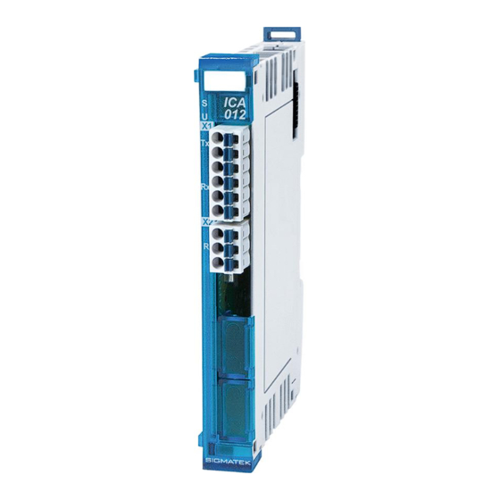
- Page 3 ICA 012 with 1 galvanically separated CAN bus 1 switchable CAN bus terminating resistor The S-DIAS interface module ICA 012 has a gavanically separated CAN interface. The internal CAN terminating resistor can be disabled via the software or a wire jumper.
-
Page 4: Table Of Contents
CAN Bus Station Number ............25 Number of CAN Bus Participants ..........25 CAN Bus Data Transfer Rate ............. 25 CAN Bus Termination ..............26 Connection to the ICA 012 ............26 Wiring ..................28 Shielding ..................28 Page 2 26.07.2023... - Page 5 S-DIAS INTERFACE MODULE ICA 012 Mounting ................29 Supported Cycle Times ............32 Cycle Times below 1 ms (in µs) ..........32 Cycle Times equal to or higher than 1 ms (in ms) ....32 Hardware Class ICA012 ............33 General Information ..............
- Page 6 ICA 012 S-DIAS INTERFACE MODULE 9.4.16 ChkObjExists ..................42 9.4.17 DelCanObj ..................42 9.4.18 DelBasicCanObj ................42 Asynchrones Interface ............... 43 9.5.1 IsInstalled ..................43 9.5.2 GetBaudrate ..................43 9.5.3 SetBaudrate ..................44 9.5.4 AddCanObj ..................44 9.5.5 InitBasicCanObject ................45 9.5.6...
- Page 7 S-DIAS INTERFACE MODULE ICA 012 Internal Properties ..............52 9.9.1 Initialization of CAN Objects.............. 52 9.9.2 Isochronous Communication............. 52 9.9.3 Asynchronous Communication ............52 9.9.4 Error Codes..................52 9.9.5 Asynchronous Sending and Receiving ..........52 9.9.6 Time Response Sending/Receiving ..........54 9.10...
-
Page 8: Technical Data
General knowledge of automation technology is required. Further help and training information, as well as the appropriate accessories can be found on our website www.sigmatek-automation.com. Our support team is happily available to answer your questions. Please see our website for our hotline number and business hours. - Page 9 S-DIAS INTERFACE MODULE ICA 012 Basic Safety Directives Symbols Used The following symbols are used in the operator documentation for warning and danger messages, as well as informational notes: DANGER Danger indicates that death or serious injury will occur, if the specified measures are not taken.
- Page 10 ICA 012 S-DIAS INTERFACE MODULE INFORMATION Information Provides important information on the product, handling or relevant sections of the documentation, which require attention. Page 8 26.07.2023...
- Page 11 It does not guarantee properties under the warranty. Please thoroughly read the corresponding documents and this operating manual before handling a product. SIGMATEK GmbH & Co KG is not liable for damages caused through, non-compliance with these instructions or applicable regulations.
- Page 12 ICA 012 S-DIAS INTERFACE MODULE General Safety Directives The Safety Directives in the other sections of this operating manual must be observed. These instructions are visually emphasized by symbols. INFORMATION According to EU Directives, the operating manual is a component of a product.
- Page 13 S-DIAS INTERFACE MODULE ICA 012 CAUTION Handle the device with care and do not drop or let fall. Prevent foreign bodies and fluids from entering the device. The device must not be opened! Manipulez l’appareil avec précaution et ne le laissez pas tomber.
- Page 14 The product was constructed in compliance with the following European Union directives and tested for conformity. 3.1.1 EU Conformity Declaration EU Declaration of Conformity The product ICA 012 conforms to the following European directives: • 2014/35/EU Low-voltage Directive • 2014/30/EU Electromagnetic Compatibility (EMC Directive) •...
- Page 15 S-DIAS INTERFACE MODULE ICA 012 Type Plate HW: Hardware version SW: Software version 26.07.2023 Page 13...
-
Page 16: Performance Data
ICA 012 S-DIAS INTERFACE MODULE Technical Data Performance Data Interfaces 1x CAN 1x Termination connection Adjustable data transfer rates 20,000 Baud; 50,000 Baud; 100,000 Baud; 125,000 Baud; 250,000 Baud; 500,000 Baud; 615,000 Baud; 1,000,000 Baud; Overvoltage protection Pin CAN H ±30 V... -
Page 17: Electrical Requirements
S-DIAS INTERFACE MODULE ICA 012 Electrical Requirements Power supply +24 V +18-30 V DC Voltage supply from the S-DIAS +5 V Current consumption on the typically 60 mA maximum 70 mA S-DIAS bus (+5 V supply) Voltage supply from the S-DIAS... - Page 18 ICA 012 S-DIAS INTERFACE MODULE UL Certification INFORMATION For USA and Canada: The supply must be limited to: a) max. 5 A at voltages from 0-20 V DC, or b) 100 W at voltages from 20-60 V DC The limiting component (e.g. transformer, power supply or fuse) must be certified by an NRTL (Nationally Recognized Testing Laboratory).
- Page 19 S-DIAS INTERFACE MODULE ICA 012 26.07.2023 Page 17...
-
Page 20: Miscellaneous
ICA 012 S-DIAS INTERFACE MODULE Miscellaneous Article number 20-102-012 Standard UL in preparation Environmental Conditions Storage temperature -20 ... +85 °C Environmental temperature 0 ... +55 °C Humidity 0-95 %, non-condensing Installation altitude above sea 0-2000 m without derating level >... -
Page 21: Mechanical Dimensions
S-DIAS INTERFACE MODULE ICA 012 Mechanical Dimensions 26.07.2023 Page 19... -
Page 22: Connector Layout
ICA 012 S-DIAS INTERFACE MODULE Connector Layout Page 20 26.07.2023... -
Page 23: Status Leds
S-DIAS INTERFACE MODULE ICA 012 Status LEDs Module Status green module active no supply available BLINKING (5 Hz) no communication User yellow can be set from the application (e.g. the module LED can be set to blinking through the visualization so that the module is easily found in the control... -
Page 24: Applicable Connectors
ICA 012 S-DIAS INTERFACE MODULE Applicable Connectors Connectors: X1-X2: Connectors with spring terminals (included in delivery) The spring terminals are suitable connecting ultrasonically compacted (ultrasonically welded) strands. Connections: Stripping length/Sleeve length: 10 mm Mating direction: parallel to the conductor axis or circuit board Conductor cross section rigid: 0.2-1.5 mm... -
Page 25: Label Field
S-DIAS INTERFACE MODULE ICA 012 Label Field Manufacturer Weidmüller Type MF 10/5 CABUR MC NE WS Weidmüller article number 1854510000 Compatible printer Weidmüller Type Printjet Advanced 230V Weidmüller article number 1324380000 26.07.2023 Page 23... -
Page 26: Wiring
ICA 012 S-DIAS INTERFACE MODULE Wiring Example Connection Page 24 26.07.2023... -
Page 27: Can Bus Setup
S-DIAS INTERFACE MODULE ICA 012 CAN Bus Setup This section explains how to correctly configure the CAN bus. The following parameters must first be set: Station number and data transfer rate. CAN Bus Station Number Each CAN bus station is assigned its own station number. With this station number, data can be exchanged with other stations connected to the bus. -
Page 28: Can Bus Termination
A terminator is located in the ICA 012, which is activated when connector X2 is open (=> no jumper from X2 TERM+ to TERM-). This means that if the ICA 012 is connected at the end of the CAN bus, no external 120 Ω terminator on X1 is required. - Page 29 S-DIAS INTERFACE MODULE ICA 012 If no jumper wire is set, the internal 120 Ω CAN bus terminator is activated (located between CAN A (LOW) and CAN B (HIGH)). 26.07.2023 Page 27...
-
Page 30: Wiring
ICA 012 S-DIAS INTERFACE MODULE 10 Wiring • The 120 Ω terminating resistors must be placed at each bus end, whereby the ICA 012 already has a built-in terminator (with TERM +/- for deactivation). • Star wiring must be avoided 10.1 Shielding... - Page 31 S-DIAS INTERFACE MODULE ICA 012 11 Assembly/Installation 11.1 Check Contents of Delivery Ensure that the contents of the delivery are complete and intact. See chapter 1.3 Contents of Delivery. INFORMATION On receipt and before initial use, check the device for damage. If the device is damaged, contact our customer service and do not install the device in your system.
-
Page 32: Mounting
ICA 012 S-DIAS INTERFACE MODULE 11.2 Mounting The S-DIAS modules are designed for installation into the control cabinet. To mount the modules a DIN-rail is required. The DIN rail must establish a conductive connection with the back wall of the control cabinet. The individual S-DIAS modules are mounted on the DIN rail as a block and secured with latches. - Page 33 S-DIAS INTERFACE MODULE ICA 012 Recommended minimum distances of the S-DIAS modules to the surrounding components or control cabinet wall: a, b, c … distances in mm (inches) 26.07.2023 Page 31...
-
Page 34: Supported Cycle Times
ICA 012 S-DIAS INTERFACE MODULE 12 Supported Cycle Times 12.1 Cycle Times below 1 ms (in µs) x= supported 12.2 Cycle Times equal to or higher than 1 ms (in ms) x= supported x= supported Page 32 26.07.2023... -
Page 35: Hardware Class Ica012
13 Hardware Class ICA012 Hardware Class ICA012 for the S-DIAS ICA012 CAN module This hardware class is used to control the ICA 012 hardware module with a CAN interface (galvanically isolated). More information on the hardware can be found in the module documentation. -
Page 36: General Information
ICA 012 S-DIAS INTERFACE MODULE 13.1 General Information Class State State Shows the actual status of the hardware class. Device ID State Shows the Device ID of the hardware module FPGA version State FPGA version of the module in 16#XY (e.g. 16#10 = version 1.0). -
Page 37: Can Interface
S-DIAS INTERFACE MODULE ICA 012 13.2 CAN Interface Property Activates the internal CAN terminator. Termination deactivate internal terminating resistance activate internal terminating resistance as initialization value Baudrate Can Property The baud rate setting for the 1st CAN bus interface: Client... -
Page 38: Communication Interfaces
ICA 012 S-DIAS INTERFACE MODULE State Shows the status of the CAN termination resistance Termination termination resistance off State termination resistance on Receive Buffer State Indicates whether the asynchronous CAN receive buffer has overflowed. Overflow Occurs when more asynchronous CAN objects were received than the available space in the buffer. -
Page 39: Isochroneous Interface
S-DIAS INTERFACE MODULE ICA 012 13.4 Isochroneous Interface 13.4.1 IsInstalled Returns whether the CAN interface is installed. Return parameters Type Description retval DINT CAN Interface is installed the interface in this variant of the hardware is not available 13.4.2 GetBaudrate This function provides the baud rate of the CAN interface. -
Page 40: Setbaudrate
ICA 012 S-DIAS INTERFACE MODULE 13.4.3 SetBaudrate This function is used to set the baud rate of the CAN interface. Transfer parameters Type Description us_BaudRate USINT 615 kBit/s 500 kBit/s 250 kBit/s 125 kBit/s 100 kBit/s 50 kBit/s 20 kBit/s... -
Page 41: Cantxobject
S-DIAS INTERFACE MODULE ICA 012 13.4.5 CanTxObject Sends an object to the CAN bus. Transfer parameters Type Description ObjNr Object number (max. 2047) length USINT Data length (max. 8) data PVOID Pointer to the data Return parameters Type Description retval Function successful ≠0... -
Page 42: Cantxobjectextended
ICA 012 S-DIAS INTERFACE MODULE 13.4.7 CanTxObjectExtended Sends an object to the CAN bus, which uses an Extend identifier (29-bit ObjNr instead of the 11-bit ObjNr). An object channel to the _SdiasCanIsoInterface class is required therefore. Transfer parameters Type Description... -
Page 43: Initbasiccanobject
S-DIAS INTERFACE MODULE ICA 012 13.4.11 InitBasicCanObject Not supported by the isochronous interface. Return parameters Type Description retval DINT function not supported 13.4.12 Set_RTR_Flag Not supported by the isochronous interface. Return parameters Type Description retval DINT function not supported 13.4.13 CanTxObjHandle Not supported by the isochronous interface. -
Page 44: Chkobjexists
ICA 012 S-DIAS INTERFACE MODULE 13.4.16 ChkObjExists Not supported by the isochronous interface. Return parameters Type Description retval DINT function not supported 13.4.17 DelCanObj Not supported by the isochronous interface. Return parameters Type Description retval DINT function not supported 13.4.18 DelBasicCanObj Not supported by the isochronous interface. -
Page 45: Asynchrones Interface
S-DIAS INTERFACE MODULE ICA 012 13.5 Asynchrones Interface 13.5.1 IsInstalled Returns whether the CAN interface is installed. Return parameters Type Description retval DINT CAN Interface is installed the interface in this variant of the hardware is not available 13.5.2 GetBaudrate This function provides the baud rate of the CAN interface. -
Page 46: Setbaudrate
ICA 012 S-DIAS INTERFACE MODULE 13.5.3 SetBaudrate This function is used to set the baud rate of the CAN interface. Transfer parameters Type Description us_BaudRate USINT 615 kBit/s 500 kBit/s 250 kBit/s 125 kBit/s 100 kBit/s 50 kBit/s 20 kBit/s... -
Page 47: Initbasiccanobject
S-DIAS INTERFACE MODULE ICA 012 13.5.5 InitBasicCanObject Adds a Receive object to the CAN bus. This function also installs the filter to detect more than one CAN object. Transfer parameters Description ObjNr Object number (max. 2047) mask USINT Bit mask to select CAN objects... -
Page 48: Addcanobjextended
ICA 012 S-DIAS INTERFACE MODULE 13.5.7 AddCanObjExtended Adds a Send or Receive object to the CAN bus, which uses an Extend identifier (29-bit ObjNr instead of the 11-bit ObjNr). An object channel to the _SdiasCanAsyInterface class is required therefore. Transfer parameters... -
Page 49: Cantxobjectextended
S-DIAS INTERFACE MODULE ICA 012 13.5.9 CanTxObjectExtended Sends an object to the CAN bus, which uses an Extend identifier (29-bit ObjNr instead of the 11-bit ObjNr). An object channel to the _SdiasCanAsyInterface class is required therefore. Transfer parameters Type Description... -
Page 50: Set_Rtr_Flag
ICA 012 S-DIAS INTERFACE MODULE 13.5.13 Set_RTR_Flag Sets the Remote Transmit Request flag of the receiving object. So a request is sent to the according sending object. After receiving the object the RTR flag is reset. Transfer parameters Type Description... -
Page 51: Delcanobj
S-DIAS INTERFACE MODULE ICA 012 13.5.18 DelCanObj Not supported by the asynchronous interface. Return parameters Type Description retval DINT function not supported 13.5.19 DelBasicCanObj Not supported by the asynchronous interface. Return parameters Type Description retval DINT function not supported 26.07.2023... -
Page 52: Example Of The Interrupt Function
ICA 012 S-DIAS INTERFACE MODULE 13.6 Example of the interrupt function Transfer parameters Type Description pCanPtr ^_Basic-CanObj Pointer to the data in the CAN controller This data is hardware-dependent. rxdataptr ^_Basic-CanObj Pointer to the data that should be read before the CAN controller interrupt. -
Page 53: Basiccanobj
S-DIAS INTERFACE MODULE ICA 012 13.8 _BasicCanObj Label Data type Description CanData ARRAY [0..7] of USINT Contains received CAN data. length USINT Contains the data length of the receive object. objnumber UDINT Contains the object number of the receive object. -
Page 54: Internal Properties
ICA 012 S-DIAS INTERFACE MODULE 13.9 Internal Properties 13.9.1 Initialization of CAN Objects The CAN object must be created before the Init phase. 13.9.2 Isochronous Communication Both Send Receive objects must assigned using AddCanObj (AddCanObjectExtended). The input parameters for the Callback must be valid for the Receive objects, these are not used for Send objects. - Page 55 S-DIAS INTERFACE MODULE ICA 012 AsyTxObjectsCan: Per cycle, as many CAN objects are sent as are entered in this client (hardware classes buffer size = 32). AsyRxObjectsCan: Per cycle, as many CAN objects are received as are entered in this client (ICA buffer size = 157).
-
Page 56: Time Response Sending/Receiving
ICA 012 S-DIAS INTERFACE MODULE 13.9.6 Time Response Sending/Receiving 13.9.6.1 Sdias Local ISO 1. User class sends data. 2. Data is written in the CCA module. 3. Data are sent on the CAN bus. 4. Data packet 1 is received at the CAN bus. - Page 57 S-DIAS INTERFACE MODULE ICA 012 13.9.6.2 S-DIAS Lokal ASY 1. User class sends data. 2. Data is written in the CCA module. 3. Data are sent on the CAN bus. 4. Data packet 1 is received at the CAN bus.
- Page 58 ICA 012 S-DIAS INTERFACE MODULE 13.9.6.3 S-DIAS via VARAN ISO 1. User class processes data. 2. Data are set by the VARAN bus. 3. Data is written in the CCA module. 4. Data are sent on the CAN bus. 5. Data packet 1 is received at the CAN bus.
- Page 59 S-DIAS INTERFACE MODULE ICA 012 13.9.6.4 S-DIAS via VARAN ASY 1. User class processes data. 2. Data are sent via VARAN bus. 3. Data is written in the CCA module. 4. Data are sent at CAN-Bus. 5. Data packet 1 is received at the CAN bus.
-
Page 60: Appendix
ICA 012 S-DIAS INTERFACE MODULE 13.10 Appendix Examples of bit masks for InitBasicCanObject: Mask 16#FFF0, ObjNr 16#0000 – => Received objects: 16#0000 16#000F Mask 16#FFF0, ObjNr 16#00F0 – => Received objects: 16#00F0 16#00FF Mask 16#0000, ObjNr required => Receive objects:... - Page 61 S-DIAS INTERFACE MODULE ICA 012 14 Transport/Storage INFORMATION This device contains sensitive electronics. During transport and storage, high mechanical stress must therefore be avoided. For storage and transport, the same values for humidity and vibration as for operation must be maintained! Temperature and humidity fluctuations may occur during transport.
- Page 62 ICA 012 S-DIAS INTERFACE MODULE 16 Maintenance INFORMATION During maintenance as well as servicing, observe the safety instructions from chapter 2 Basic Safety Directives. 16.1 Service This product was constructed for low-maintenance operation. 16.2 Repair INFORMATION In the event of a defect/repair, send the device with a detailed error description to the address listed at the beginning of this document.
- Page 63 S-DIAS INTERFACE MODULE ICA 012 Documentation Changes Change date Affected Chapter Note page(s) 17.02.2017 3 Connector Layout LED colors 17.08.2017 1.4 Environmental Conditions Pollution Degree 3.2 Applicable Connectors Sleeve length added Added info regarding ultrasonically welded strands 18.10.2017 3.3 Label Field...
Need help?
Do you have a question about the ICA 012 and is the answer not in the manual?
Questions and answers