
Subscribe to Our Youtube Channel
Related Manuals for CAME Ozak GARD Series


Summary of Contents for CAME Ozak GARD Series
- Page 1 ÖZAK CAME.COM/OZAK Automatic barrier FA01580-EN - GARD series G4000T INSTALLATION MANUAL EN English...
- Page 3 GENERAL PRECAUTIONS FOR INSTALLERS ⚠ CAUTION! Important safety instructions. Follow all of these instructions. Improper installation can cause serious bodily harm. Before continuing, also read the general precautions for users. This product must only be used for its specifically intended purpose. Any other use is dangerous. ÖZAK is not liable for any damage caused by improper, wrongful and unreasonable use.
-
Page 4: Operating Limits
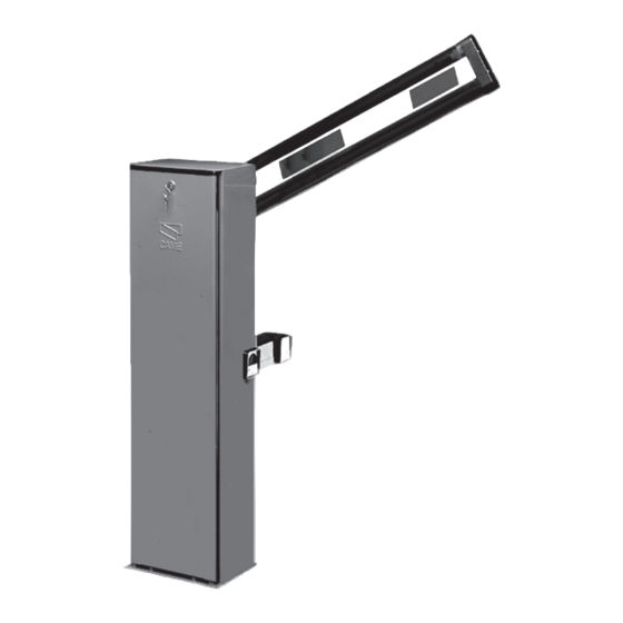
This symbol shows which parts to read carefully. ⚠ This symbol shows which parts describe safety issues ☞ This symbol shows which parts to tell users about. The measurements, unless otherwise stated, are in millimeters. DESCRIPTION Barrier made of painted, galvanized steel or satin-finish, stainless steel, set up to take accessories. REQUEST EITHER LEFT OR RIGHT-HAND BARRIERS WHEN ORDERING. -
Page 5: Standard Installation
DESCRIPTION OF PARTS 1. Cabinet 2. Anchoring plate 3. Motor-shaft plate 4. Release lock 5. Gear motor 6. Balancing spring 7. Mechanical stops 8. Limit-switches 9. Control panel 10. Anchoring braces STANDARD INSTALLATION 1. Barrier 7. Photocells post 2. Flashing light 8. -
Page 6: Preliminary Checks
GENERAL INSTRUCTIONS FOR INSTALLING ⚠ Only skilled, qualified staff must install this product. PRELIMINARY CHECKS ⚠ Before beginning, do the following: • make sure the plate is anchored to a solid spot; • checkthat there are no obstructions or impediments near the cabinet; • set up suitable tubes and conduits for the electric cables to pass through, making sure they are protected from any mechanical damage. - Page 7 Set up a foundation frame that is larger than the anchoring plate and sink it into the dug hole. Fit an iron cage into the foundation frame to reinforce the concrete. Assemble the four anchoring braces to the anchoring plate. M12 UNI5588 Washer M12x40 UNI 5739...
- Page 8 Place the cabinet onto the anchoring plate and fasten it using nuts and washers. M12 UNI 5588 Washer To change the rotation at a later date, request the documentation from your local retailer or contact Came in your Country (see the last page or visit www.came.com) Entry side...
- Page 9 Fit the boom-brace cover to the drive-shaft plate; use only one bolt and leave it loosened. Fit the boom into the boom-brace cover. UNI 5931 M8x20 Raise the boom vertically and tighten the remaining bolts.
- Page 10 BALANCING THE BOOM The barrier comes with a standard spring hooked to position B. Before proceeding, check that the spring you have chosen is suitable for the accessories and the clearance. ⚠ When configuring the barrier, make sure the gear motor is locked! Hooking the springs Boom...
- Page 11 To precision balance the barrier, first release the gear motor and loosen the rod nut. Manually turn the spring to increase or reduce the traction. The boom should stabilize at 45°. Fit the nut to fasten the rod to the spring and tighten it. Lock the gear motor once again.
-
Page 12: Control Panel
CONTROL PANEL ⚠ Caution! Before working on the control panel, cut off the mains power supply and remove any batteries. Power supply to the control panel and control devices: 24 V AC/DC. Use DIP switches to set functions and the trimmer for adjustments. All wiring connections are quick-fuse protected. -
Page 13: Electrical Connections
⚠ The electrical cables must not touch any heated parts such as the motor, transformer, and so on. FACTORY WIRING The gear motor is already connected. To install the barrier on the right side, ask your local retailer for the documentation needed or contact Came in your country, see www.came.com 24 V DC gear motor... -
Page 14: Control Devices
SIGNALING DEVICES Output to notify the state of the barrier (Contact rated for: 24 V AC - 3 W max.). it warns of the booms raised position, and switches off when the boom is lowe- red. Output for flashing light (Contact rated for: 24 V - 32 W max). It flashes when the boom is moving. -
Page 15: Safety Devices
SAFETY DEVICES Photocells Configure NC contact/s C1 and/or C5, input for safety accessories such as photocells. C1 reopening while closing. When the boom is closing, opening the contact causes its movement to invert until fully opened; If unused, shortcircuit contact 2-C1. C5 immediate closing. - Page 16 ESTABLISHING THE LIMIT-SWITCH POINTS Close the inspection hatch and power up the system. Move the boom the check that it is parallel to the road surface when closed and at about 89° when open. ⚠ The barrier's opening and closing maneuvers must be performed with the inspection hatch closed. For opening: - release the gear motor;...
- Page 17 PROGRAMMING FUNCTIONS Default settings 1 2 3 4 5 6 7 8 9 10 3 4 5 6 7 8 9 10 DIP-SWITCH Description of functions 1 ON AUTOMATIC CLOSING; set 1 to OFF to deactivate it 2 ON ONLY OPEN from button 2-7 and/or from transmitter (with AF card fitted) 2 OFF OPEN-CLOSE-INVERT from the button on 2-7 and/or from a transmitter (with AF card fitted) 3 ON...
- Page 18 ACTIVATING THE RADIO CONTROL Connect the RG58 cable antenna cable to the corresponding terminals . For TOP and TAM series transmitting on 433.92 MHz, set the jumper-switch of the AF43S card as shown in the figure . Plug the AF card, that is, the AF43S or the AF868 into the connector on the control board . ⚠...
-
Page 19: Adjusting The Speed
ADJUSTING THE SPEED Min. = minimum Med. = medium Max. = maximum COM = common DIS. 27370 Max. Med. Min. Min. Max. To regulate the travel speed, move To adjust the slow-down speed, faston A on Min., Med. or Max. move faston B to Min. - Page 20 PAIRED CONNECTION WITH A SINGLE COMMAND Establish the MASTER, that is, the motor that drives both barriers, and SLAVE , that is, the motor piloted by the MASTER motor. SLAVE MASTER On the MASTER barrier's electronic board, make the necessary electrical connections, activate the radio control, program the functions and settings.
-
Page 21: Troubleshooting
Connect the two control boards using terminals RX-TX-GND as shown in the figure. Black Screened cable 2402C 22AWG- type cables Black RX TX GND E +10 -11 1 7 C1 C5 CONTROL BOARD SLAVE RX TX GND E +10 -11 1 7 C1 C5 CONTROL BOARD MASTER TROUBLESHOOTING... -
Page 22: Dismantling And Disposal
DISMANTLING AND DISPOSAL ☞ Our facilities comply with national environmental legislations and regulations. Please continue protecting the environment and follow the disposal guidelines below. DISPOSING OF THE PACKAGING The packaging materials (cardboard, plastic, and so on) should be disposed of as solid household waste, and simply separated from other waste for recycling. - Page 23 �� O" • CAME S.p as, rnpegna a trasmettere • ., ri5poolD a una nchoesta �-• moL,,i:a dele BU10<,1a � � pen..,.,b stJle quos, maa:lwle. e / came Sp A..1010',.,ng a cU1 rrotrlO!ed from the natorol auchor,IJOs. � to Pffl'.ide inlormat>on related to the quas, maclwles. and/ Do fwma came s p ,-e,pllchtet SICh aut ..., a,gemessen...
- Page 24 ÖZAK Geçiş Teknolojileri San. Tic. A.Ş. Köseköy, Çuhane Cd. No:130 41080 ÖZAK Kartepe - Kocaeli / Türkiye T & F +90 (0)262 373 48 48 (PBX) CAME.COM/OZAK...
Need help?
Do you have a question about the Ozak GARD Series and is the answer not in the manual?
Questions and answers