CAME GARD Series Installation Manual
Hide thumbs
Also See for GARD Series:
- Installation manual (97 pages) ,
- Manual (24 pages) ,
- Standard installation (12 pages)
Table of Contents
Advertisement
Advertisement
Table of Contents

Related Manuals for CAME GARD Series


Summary of Contents for CAME GARD Series
- Page 1 Automatic barrier FA01118-EN GARD series G12000 English INSTALLATION MANUAL...
- Page 3 Before continuing, also read the general precautions for users. This product must only be used for its specifi cally intended purpose. Any other use is dangerous. Came S.P.A. is not liable for any damage caused by improper, wrongful and unreasonable use. • This manual's product is defi ned by machinery directive 2006/42/CE as "partly-completed machinery".
-
Page 4: Intended Use
This symbol shows which parts to read carefully. ⚠ This symbol shows which parts describe safety issues ☞ This symbol shows which parts to tell users about. The measurements, unless otherwise stated, are in millimeters. DESCRIPTION Barrier made of galvanized varnished steel, with control panel. INTENDED USE This automatic barrier is designed for special or very large passages. -
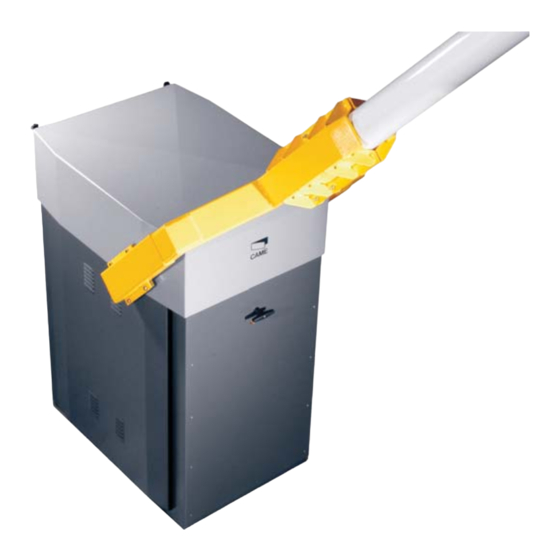
Page 5: Description Of Parts
DESCRIPTION OF PARTS 1. Cabinet 2. Fastening counter base 3. Boom-latching flange 4. Release lock 5. Gear motor 6. Counterweights 7. Drive arm 8. Transmission gears 9. Control panel 10. Boom 11. Anchoring braces STANDARD INSTALLATION 1. Barrier 7. Small post 2. -
Page 6: Preliminary Checks
GENERAL INSTALLATION INDICATIONS ⚠ Only skilled, qualified staff must install this product. PRELIMINARY CHECKS ⚠ Before beginning, do the following: • make sure the plate is anchored to a solid spot; • checkthat there are no obstructions or impediments near the cabinet; • set up suitable tubes and conduits for the electric cables to pass through, making sure they are protected from any mechanical damage. - Page 7 Dig a hole for the foundation frame. Set up the corrugated tubes needed for the wiring coming out of the junction pit. The number of tubes depends on the type of system and the accessories you are going to fit. Set up a foundation frame that is larger than the anchoring plate and sink it into the dug hole.
- Page 8 Fill the hole with earth around the concrete block. Remove the nut and washer from the bolts Run the electrical cables into the tubes until they exit by about 1,500 mm. PREPARING THE BARRIER Loosen the screws on the cover, and remove it. Take hold of the side, lift it a few centimeters and then slide it out by holding it from beneath.
- Page 9 Establish the LTP DISTANCE of the ø100 mm inner-tube by applying the given formula, then cut and measure and fi t the end cap. - 5850 outer tube fi tting depth end cap fi xed length of 6,200 mm inner tube Assemble the boom by fi...
- Page 10 d) Use a sawhorse and the fi xed rest to position the barrier along a) Position and fasten the barrier's fi xed rest; it should be perfectly aligned lengthwise with the cabinet. its operating axis. b) Mount the fork while joining the two tube clamps to the boom, e) Check and adjust any imperfections, then tighten all the nuts leave the nuts loose.
-
Page 11: Control Panel
CONTROL PANEL ⚠ Caution! Before working on the control panel, cut off the mains power supply and remove any batteries. Power supply to the control panel and control devices: 24 V AC/DC. Use DIP switches to set functions and the trimmer for adjustments. All wiring connections are quick-fuse protected. -
Page 12: Electrical Connections
⚠ The electrical cables must not touch any heated parts such as the motor, transformer, and so on. FACTORY WIRING The gear motor is already connected. To install the barrier on the right side, ask your local retailer for the documentation needed or contact Came in your country, see www.came.com 24 V DC gear motors... -
Page 13: Control Devices
CONTROL DEVICES STOP button (NC contact). For stopping the boom while excluding the automatic closing. To resume movement either press the control button or any other control device. If unused, set DIP switch 9 to ON. OPEN ONLY function from control device with NO contact. Warning: in MAINTAINED ACTION mode, the control device must be connected to 2-3. - Page 14 SIGNALING DEVICES Output to notify the state of the barrier (Contact rated for: 24 V AC - 3 W max.). it warns of the booms raised position, and switches off when the boom is lowe- red. Output for flashing light (Contact rated for: 24 V - 32 W max). It flashes when the boom is moving.
- Page 15 PROGRAMMING FUNCTIONS Default settings 3 4 5 6 7 8 9 10 DIP-SWITCH Description of functions 1 ON AUTOMATIC CLOSING; set 1 to OFF to deactivate it 2 ON ONLY OPEN from button 2-7 and/or from transmitter (with AF card fitted) 2 OFF OPEN-CLOSE-INVERT from the button on 2-7 and/or from a transmitter (with AF card fitted) 3 ON...
- Page 16 ACTIVATING THE RADIO CONTROL Connect the RG58 cable antenna cable to the corresponding terminals For TOP and TAM series transmitting on 433.92 MHz, set the jumper-switch of the AF43S card as shown in the figure Plug the AF card, that is, the AF43S or the AF868 into the connector on the control board ⚠...
-
Page 17: Final Operations
FINAL OPERATIONS Once the electrical connections are done and the barrier is operational, fi t the cover and fasten it by using the screws. Replace the inspection hatch and the upper cover. Close the hatch and fasten the cover by using the screws. TROUBLESHOOTING PROBLEM REFERENCE... - Page 18 PAIRED CONNECTION WITH A SINGLE COMMAND Establish the MASTER, that is, the motor that drives both barriers, and SLAVE , that is, the motor piloted by the MASTER motor. SLAVE MASTER On the MASTER barrier's electronic board, make the necessary electrical connections, activate the radio control, program the functions and settings.
-
Page 19: Dismantling And Disposal
☞ CAME CANCELLI AUTOMATICI S.p.A. applies a certified Environmental Management System at its premises, which is compliant with the UNI EN ISO 14001 standard to ensure the environment is safeguarded. Please continue safeguarding the environment. At CAME we consider it one of the fundamentals of our operating and market strategies. Simply follow these brief disposal guidelines:... - Page 20 The contents of this manual may change, at any time, and without notice. CAME S.p.A. Via Martiri Della Libertà, 15 31030 Dosson di Casier - Treviso - Italy tel. (+39) 0422 4940 - fax. (+39) 0422 4941...
Need help?
Do you have a question about the GARD Series and is the answer not in the manual?
Questions and answers