Table of Contents
Advertisement
Quick Links
Advertisement
Table of Contents

Subscribe to Our Youtube Channel
Related Manuals for CAME G4040EZ


Summary of Contents for CAME G4040EZ
- Page 1 AUTOMATIC BARRIERS FA 00124 -E N INSTALLATION AND OPERATION G4040EZ English...
- Page 2 • T PHYSICAL OR COGNITIVE DISABILITIES OR THOSE LACKING EXPERIENCE OR RELEVANT HIS PRODUCT MUST ONLY BE USED FOR THE PURPOSE FOR WHICH IT WAS DE . CAME S. KNOWLEDGE PROVIDED THEY ARE CLOSELY SUPERVISED OR ONCE THEY HAVE BEEN SIGNED...
-
Page 3: Intended Use
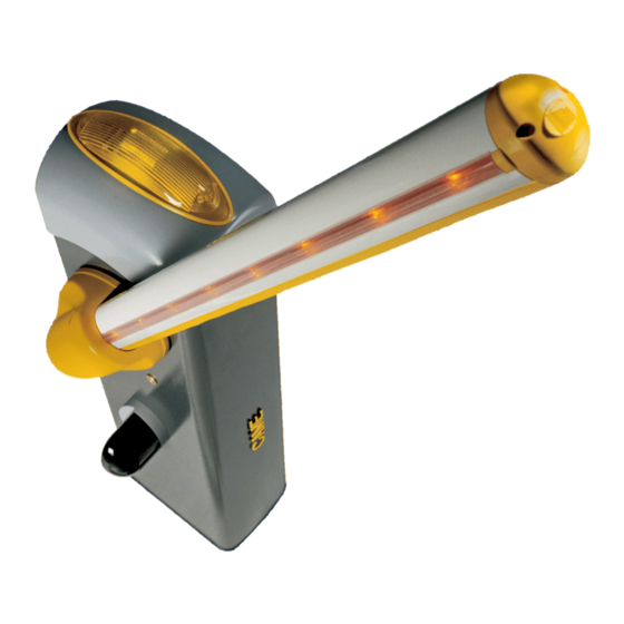
The automatic barrier is designed to be used in public and private parking facilities. Any installation and use other than that specified in this manual is forbidden. Limits to use Type G4040EZ Maximum clearance width of the passage (m) 3.75 Technical data... - Page 4 Description of parts 1. Dome cover 10. Inspection hatch 2. Motor shaft plate 11. Control panel 3. Intermediate plate 12. Boom-adjustment mechanical stop 4. Boom-attachment cover 13. Lever arm 5. Anti-shearing protective cover 14. Gearmotor with encoder 6. Cabinet 15. EMC01 filter 7.
-
Page 5: General Installation Instructions
GENERAL INSTALLATION INSTRUCTIONS ⚠ Installation must be carried out by expert qualified personnel and in full compliance with the regulations in force. Important! Using original CAME control and safety devices and accessories ensures easy installation and system maintenance. Preliminary checks ⚠... -
Page 6: Installation
INSTALLATION ⚠ The following illustrations are examples. The space for fastening the barrier and accessories varies depending on where it is installed. The installer must find the most suitable solution. ⚠ Caution! Use hoisting equipment to transport and position the barrier. During set-up and installation, the barrier could be unstable and tip over. - Page 7 Fill the hole with earth around the concrete block. Remove the nuts and washers from the bolts. Insert the electric cables into the tubes so that they protrude by about 600 mm. Preparing the barrier Remove the screws from the dome cover, insert the key in the lock and turn it anti-clockwise. Lift up the dome cover and remove the inspection hatch .
- Page 8 Installing the barrier The cabinet should be installed with the inspection hatch on the most accessible side to make any adjusting easier. Place the cabinet onto the anchoring plate and fasten it using nuts and washers. Attach the intermediate plate and boom-attachment cover to the attachment plate with a screw. Leave the screw loose to make it easier to insert the boom.
- Page 9 Fit the boom into the attachment cover and fasten it using the screws. UNI5931 M8x12 UNI5931 M8x20 Cut the groove covers to the required length and insert them in the boom conduits on both sides . Insert the shockproof rubber profile in the boom and cut off the excess . Fit the boom cap using the screws .
- Page 10 Balancing the boom Before proceeding, check that the spring you have chosen is suitable for the accessories and the clearance. PASSAGE CLEARANCE (max. 3.75 m) 001G02040 Ø 40 mm spring 001G04060 Ø 50 mm spring 001G06080 Ø 55 mm spring BOOM COMPOSITION 1.5 to 1.75 1.75 to 2.25...
- Page 11 Hook the eyelet rod onto the anchoring bracket . Release the gearmotor and manually turn the spring to increase or reduce the traction . The boom should stabilise at 45°. Fix the counter nut and lock the gearmotor again . ...
-
Page 12: Electrical Connections
ELECTRICAL CONNECTIONS ⚠ Warning! Before working on the control panel, cut off the main current supply and remove any batteries. Power supply to control panel and control devices: 24 V AC/DC. The input and output contact functions, the timing settings and user management are set and shown on the display. All connections are quick-fuse protected. -
Page 13: Power Supply
Power supply Blue Orange 230 V AC - 50/60 Hz EMC01 filter Ferrite Transformer White 24V 0 THERMAL A B GND S1 GND Power supply to accessories output: - a 24 V AC normally; - a 24 V DC when the emergency batteries are operating; Max. - Page 14 Command and control devices Black Transponder or card reader Blue White Keypad selector OPEN-CLOSE-INVERT (step-by-step) function from control device (N.O. contact). CLOSE function from control device (N.O. contact). Warning: in HOLD-TO-RUN mode, the control device must be connected to 2-4. Warning! OPEN function from control device (N.O.
-
Page 15: Signalling Devices
Signalling devices Open-barrier signal output (contact rating: 24 V AC - 3 W max). It shows the barrier status (function F 10). Luminous cord (contact rating: 24 V AC - 32 W max). It flashes when the boom opens and closes (function F 15). Additional light connection output (contact rating: 24 V AC - 25 W max): - dome flashing light: it flashes when the barrier opens and closes. - Page 16 2 3 3P 4 5 7 CX CY 10 11 E1 E6 Rx Tx 1 2 3 3P 4 5 7 CX CY Connection for paired or alternate operation and for Came Remote Protocol (CRP only for ZL39EX) UTP CAT 5 Insert the RSE card.
- Page 17 Establishing the limit-switch points Close the inspection hatch and power the system. Activate the boom to check whether it is parallel to the road surface when closed and at about 89° when open. ⚠ The inspection hatch must be closed when the boom opens and closes. To correct the vertical position of the boom: - lower the boom;...
- Page 18 PROGRAMMING ⚠ During programming, the barrier must be stopped. Description of setting commands Display S1 GND The ENTER key is for: The ESC key is for: - entering the menu; - exiting the menu; - confirming and saving the values set. - cancelling modifications.
-
Page 19: Functions Mapping
Functions mapping Total stop function (1-2) Function associated with CX input Function associated with CY input Safety test function Hold-to-run function Obstruction detection function with motor idle F 10 Function associated with the open-barrier signal output F 11 Exclude encoder F 14 Sensor type selection function F 15... - Page 20 F6 Hold-to-run 0 = Deactivated (default) / 1 = Activated Press and hold a button to open and close the barrier. Opening button on contact 2-3; closing button on contact 2-4. All other command devices, including radio-controlled devices, are excluded. F9 Obstruction detection 0 = Deactivated (default) / 1 = Activated with motor idle...
- Page 21 This function only appears if function F 49 is set to PAIRED or ALTERNATE operation. F56 Peripheral number 1 ----> 225 For systems with more than one automation device using a CRP (Came Remote Protocol) connection system, set an address between 1 and 225 for each panel. F60 Sleep mode 0 = Deactivated (default) / 1 = Activated To reduce the energy consumption in stand-by.
-
Page 22: Motor Test
Delete all users. A 1 Set boom type 0 = booms with a joint / 2 = boom 2 m / 4 = boom 4 m / 6 = boom 6 m / 8 = boom 8 m To define the type of boom. ⚠ ... -
Page 23: Travel Calibration
Travel calibration Before calibrating the travel, identify the type of boom, check that the boom is balanced and check that the manoeuvring area is clear of any obstacles. Important! During calibration, all safety devices will be disabled, excluding the TOTAL STOP device. 1. - Page 24 When entering/deleting users, the flashing numbers that appear are numbers that can be used for other users you may want to enter (maximum 25 users). Entering a user with an associated command User Associated com- mand 1. Select U 1. Press ENTER to confirm.
-
Page 25: Final Operations
Memory roll card This saves the user and system-configuration data so that they can be reused with another electronic circuit board, including in another system. After saving the data, remove the memory roll. Memory roll. FINAL OPERATIONS Once you have finished with the connections and started up the operator, fit the cover on the panel and fasten with the screws . Reposition the inspection hatch and dome cover . - Page 26 PAIRED CONNECTION Important! First do the following on both operators: - insert the RSE card (with the dipswitches set to OFF) on the panel connector on both operators. - connect the two boards with a CAT 5 cable (max. 1,000 m) to terminals A-A / B-B / GND-GND; see CONNECTION FOR PAIRED OR ALTERNATE OPERATION) - connect all command and safety devices on the MASTER operator panel.
-
Page 27: Alternate Connection
ALTERNATE CONNECTION Important! First do the following on both operators: - insert the RSE card (with the dipswitches set to OFF) on the panel connector on both operators. - connect the two boards with a CAT 5 cable (max. 1,000 m) to terminals A-A / B-B / GND-GND; see CONNECTION FOR PAIRED OR ALTERNATE OPERATION) Connect the safety and control devices with the OPEN function (contact 2-3) and STEP-BY-STEP (contact 2-7) on the panel on the MASTER operator. -
Page 28: Error Messages
ERROR MESSAGES The error messages appear on the display or are flagged by an LED The travel calibration was interrupted by the STOP button being activated. Encoder broken. Services test error. Insufficient working time. Maximum number of obstructions detected. Overheating of transformer / inspection hatch open / boom released from gearmotor. Encoder excluded. -
Page 29: Maintenance Log
MAINTENANCE LOG Periodic maintenance ☞ Before doing any maintenance, disconnect the power supply, to prevent any hazardous situations caused by the boom moving accidentally. Periodic maintenance log to be filled in by users every six months. Date Notes Signature... - Page 30 Extraordinary maintenance ⚠ The following table is for logging any extraordinary maintenance jobs, repairs and improvements performed by specialised contractors. Any extraordinary maintenance jobs must only be carried out by specialised technicians. Extraordinary maintenance log Fitter's stamp Name of operator Job performed on (date) Technician's signature Requester's signature...
-
Page 31: Decommissioning And Disposal
DECOMMISSIONING AND DISPOSAL ☞ CAME S.p.A. employs a certified environmental management system at its premises, compliant with the UNI EN ISO 14001 standard, to ensure the environment is safeguarded. Please continue safeguarding the environment. At CAME we consider it one of the fundamentals of our operating and market strategies. Simply... - Page 32 Came S.p.A. Came S.p.A. Via Martiri Della Libertà, 15 Via Cornia, 1/b - 1/c 31030 Dosson di Casier Dosson di Casier 33079 Sesto al Reghena Sesto al Reghena Treviso Treviso - Italy Pordenone Pordenone - Italy (+39) 0422 4940 (+39) 0434 698111...
Need help?
Do you have a question about the G4040EZ and is the answer not in the manual?
Questions and answers