
Related Manuals for CAME G2080Z


Summary of Contents for CAME G2080Z
- Page 1 BARRIERE AUTOMATICHE 1 19GU 40 Manuale d’installazione G2080Z - G2080IZ Italiano English Français Русский...
-
Page 2: Leggere Attentamente
• Il prodotto deve essere destinato solo all’uso per il quale è stato all’uso sicuro dell’apparecchio e alla comprensione dei pericoli ad esso espressamente studiato. Ogni altro uso è da considerarsi pericoloso. CAME inerenti. I bambini non devono giocare con l’apparecchio. La pulizia e la Cancelli Automatici S.p.A. -
Page 3: Riferimenti Normativi
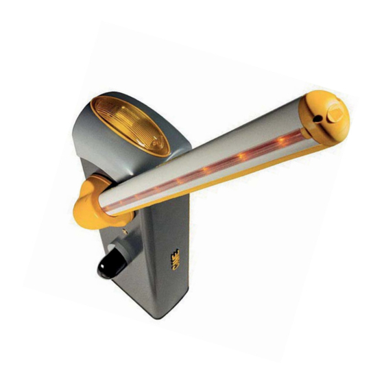
☞ Questo simbolo indica cosa comunicare all’utente. RIFERIMENTI NORMATIVI Came S.p.A. è una azienda certificata per i sistemi di gestione aziendale: qualità ISO 9001 e ambientale ISO 14001. Il prodotto in oggetto è conforme alle normative vigenti citate nella dichiarazione di conformità. - Page 4 Descrizione delle parti 1. Cupola 9. Braccio leva 2. Piastra albero motore 10. Tampone di registro asta 3. Piastra intermedia 11. Biella di trasmissione 4. Copri-attacco asta 12. Motoriduttore con encoder 5. Copertura di protezione anticesoiamento 13. Sportello di ispezione 6.
- Page 5 INDICAZIONI GENERALI PER L'INSTALLAZIONE ⚠ L’installazione deve essere effettuata da personale qualificato ed esperto e nel pieno rispetto delle normative vigenti. Importante! L’uso di dispositivi di comando, di sicurezza e di accessori originali CAME garantisce una facile installazione e manutenzione dell’impianto.
-
Page 6: Installazione
Attrezzi e materiali Assicurarsi di avere tutti gli strumenti e il materiale necessario per effettuare l’installazione nella massima sicurezza e secondo le normative vigenti. In figura alcuni esempi di attrezzatura per l’installatore. Tipi di cavi e spessori minimi Tipo di Lunghezza cavo Lunghezza cavo Lunghezza cavo... - Page 7 Preparare una cassa matta di dimensioni maggiori alla piastra di fissaggio e inserirla nello scavo. Inserire una griglia di ferro all’interno della cassa matta per armare il cemento. Assemblare le quattro zanche di ancoraggio alla piastra di fissaggio. Posizionare la piastra sopra la griglia. Riempire la cassa matta di cemento, la base deve essere perfettamente in bolla e con il filetto delle viti completamente in superficie.
- Page 8 Preparazione della barriera Inserire la chiave nella serratura e girarla in senso antiorario , sollevare la cupola e rimuovere lo sportello d’ispezione ⚠ Attenzione! La barriera è predisposta per l’installazione a sinistra. Nel caso di installazione a destra, invertire il senso di apertura dell’asta, procedendo nel seguente modo: ...
- Page 9 Installazione della barriera È consigliabile installare l’armadio con lo sportello di ispezione dal lato più pratico per eventuali interventi e regolazioni. Posizionare l’armadio sulla piastra di fissaggio e fissarlo con le rondelle e i dadi. Assemblare il copri-attacco asta, la piastra intermedia e la piastra albero motore con una vite. Lasciare la vite allentata per facilitare il successivo inserimento dell’asta.
- Page 10 Inserire la copertura di protezione anticesoiamento sul copri-attacco asta e fissarla con le viti. UNI6954 Ø 3.9x19 Bilanciamento dell’asta Prima di bilanciare l’asta, verificare, con la tabella sottostante, la congruenza tra molla scelta, accessori da applicare e luce passaggio. 400 mm LUCE PASSAGGIO (max.
- Page 11 Sbloccare il motoriduttore e posizionare l’asta in verticale. Ribloccare il motoriduttore. Installare la molla nella barriera nel seguente modo: - inserire la vite UNI5739 M12x70 nella staffa di attacco e avvitare il dado UNI5588 M12 alla vite . - avvitare la vite alla molla ; - avvitare il tirante a occhiello sotto la molla .
- Page 12 COLLEGAMENTI ELETTRICI E PROGRAMMAZIONE ⚠ Attenzione! Prima di intervenire sul quadro comando, togliere la tensione di linea e, se presenti, scollegare le batterie. Alimentazione del quadro e dei dispositivi di comando: 24 V AC/DC. Le funzioni vengono impostate con i DIP, le regolazioni con i trimmer. Tutte le connessioni sono protette da fusibili rapidi.
- Page 13 Alimentazione Morsetti per l’alimentazione degli accessori: - a 24 V AC normalmente; - a 24 V DC quando intervengono le batterie d’emergenza; Potenza complessiva consentita: 40 W 230 V AC - 50/60 Hz Capocorda a occhiello con vite e rondella per collegamento a terra Collegamento di fabbrica Il motoriduttore è...
- Page 14 Dispositivi di comando Pulsante di STOP (contatto NC). Permette l’arresto dell’asta con l’esclusione della chiusura automatica. Per riprendere il movimento premere il pulsante di comando o altro dispositivo di comando. Se non utilizzato, posizionare il DIP 9 in ON. Attenzione: in modalità...
- Page 15 Determinazione dei punti di finecorsa Chiudere lo sportello d’ispezione e dare tensione all’impianto. Azionare la barriera per verificare che l’asta sia parallela al piano stradale in posizione di chiusura e a circa 89° in posizione di apertura. ⚠ Le manovre di apertura e chiusura dell’asta, vanno eseguite con lo sportello d’ispezione chiuso! Per correggere la posizione verticale dell’asta: - abbassare asta;...
- Page 16 Attivazione del comando radio Collegare il cavo RG58 dell’antenna agli appositi morsetti . Per i trasmettitori della serie TOP, TAM e TWIN con frequenza 433,92 MHz, posizionare il jumper della scheda AF come indicato in figura . Inserire la scheda AF sul connettore della scheda elettronica . ⚠...
- Page 17 Programmazione delle funzioni Settaggio di default 3 4 5 6 7 8 9 10 Descrizione delle funzioni 1 ON CHIUSURA AUTOMATICA (1 OFF - disattivata) 2 ON SOLO APRE dal pulsante su 2-7 e/o dal trasmettitore (con scheda AF inserita) 2 OFF APRE-CHIUDE-INVERSIONE dal pulsante su 2-7 e/o dal trasmettitore (con scheda AF inserita) 3 ON...
-
Page 18: Operazioni Finali
Regolazione della velocità Min. = minimo Med. = medio Max. = massimo COM = comune DIS. 27370 Max. Med. Min. Min. Max. Per regolare la velocità di marcia, Per regolare la velocità di rallentamento, spostare il faston A su Min., Med. o Max. spostare il faston B su Min. - Page 19 SBLOCCO DELL’ASTA ⚠ L’operazione deve essere eff ettuata in assenza di tensione. Inserire la chiave nella serratura e girarla in senso orario . Alzare manualmente l’asta e ribloccarla girando la chiave in senso antiorario ⚠ ATTENZIONE! L’operazione di sblocco può rappresentare un possibile pericolo per l’utente quando, per un qualsiasi motivo -asta mal fissata alla sua sede durante il montaggio, asta divelta o spezzata da un incidente ecc.- le molle in tensione non garantiscono più...
- Page 20 COLLEGAMENTO ABBINATO CON COMANDO UNICO Stabilire la barriera Master e quella Slave. MASTER SLAVE Sulla scheda elettronica della barriera MASTER, eseguire i collegamenti elettrici, l’attivazione del comando radio, la programmazione delle funzioni e le regolazioni. MASTER 3 4 5 6 7 8 9 10 Sulla scheda elettronica della barriera SLAVE, collegare l’alimentazione su L-N, il lampeggiatore su 10-E , posizionare il DIP 7 in ON e regolare la velocità...
-
Page 21: Risoluzione Dei Problemi
Collegare le due schede utilizzando i morsetti RX-TX-GND come da fi gura. Nero Rosso Cavo schermato 2402C 22AWG Nero Rosso SCHEDA ELETTRONICA SLAVE SCHEDA ELETTRONICA MASTER RISOLUZIONE DEI PROBLEMI PROBLEMA RIFERIMENTO VERIFICA L’asta non si apre e non si chiute 1-2-3-4-6-8-18 1 - Chiudere lo sportello d’ispezione con la chiave L’asta si apre ma non si chiude... - Page 22 REGISTRI DI MANUTENZIONE Manutenzione periodica ☞ Prima di qualsiasi operazione di manutenzione, togliere la tensione, per evitare possibili situazioni di pericolo causate da accidentali movimentazioni dell’asta. Registro manutenzione periodica a cura dell’utente (semestrale) Data Annotazioni Firma...
-
Page 23: Dichiarazione Di Conformità
UNI EN ISO 14001 a garanzia del rispetto e della tutela dell’ambiente. Vi chiediamo di continuare l’opera di tutela dell’ambiente, che CAME considera uno dei fondamenti di sviluppo delle proprie strategie operative e di mercato, semplicemente osservando brevi indicazioni in materia di smaltimento: SMALTIMENTO DELL’IMBALLO... - Page 24 HU • A vállalatra, termékeire és a műszaki szervizre vonatkozó minden további információért az Ön nyelvén: HR • Za sve dodatne informacije o poduzeću, proizvodima i tehničkoj podršci: UK • Для отримання будь-якої іншої інформації про компанію, продукцію та технічну підтримку: www. came.com www. came.com CAME S.p.A.
- Page 25 1 19 GU4 0EN AUTOMATIC BARRIERS Installation manual G2080Z - G2080IZ English...
-
Page 26: Read Carefully
• Employ this product only for the use for which it was expressly made. Any moving joints and slide rails properly lubricated • Perform functional checks other use is dangerous. CAME Cancelli Automatici S.p.A is not liable for any on the photocells and sensitive safety edges, every six months. Constantly damage caused by improper, wrongful and unreasonable use •... -
Page 27: Reference Regulations
☞ This symbol shows which parts to tell users about. REFERENCE REGULATIONS Came S.p.A. the company is quality and environmentally certified by the ISO 9001 and the ISO 14001 respectively, for its management systems. This product complies with the current regulations mentioned in the declaration of conformity. - Page 28 Description of parts 1. Dome 9. Boom adjustment buffer 2. Motor-shaft plate 10. Transmission rod 3. Mid plate 11. Gearmotor with encoder 4. Boom-attachment cover Protective casing shear proof 12. Inspection hatch 5. Cabinet 13. Anchoring plate 6. Set up for fitting accessories 14.
- Page 29 CAME GENERAL INSTRUCTIONS FOR INSTALLING ⚠ Only skilled, qualified staff must install this product. Important! Using original CAME control and safety devices and accessories ensures easy installation and system maintenance. Preliminary checks ⚠ Before beginning, do the following: • make sure the plate is anchored to a solid spot;...
-
Page 30: Installation
Tools and materials Make sure you have all the tools and materials you will need for installing in total safety and in compliance with applicable regulations. The figure shows some of the equipment installers will need. Cable types and minimum thicknesses Cable length Cable length Cable length... - Page 31 Set up a foundation frame that is larger than the anchoring plate and sink it into the dug hole. Fit an iron cage into the foundation frame to reinforce the concrete. Assemble the four anchoring brackets to the anchoring plate. Place the plate over the iron cage.
- Page 32 Preparing the barrier Fit the key into the lock and turn it counter clockwise , lift the dome and remove the inspection hatch ⚠ Warning! The barrier is set up for installing on the left. When installing on the right, invert the boom's opening direction, as follows: ...
- Page 33 Installing the barrier The cabinet should be installed with the inspection hatch on the most accessible side to make any adjusting easier. Place the cabinet onto the anchoring plate and fasten it using nuts and washers. Assemble the boom-attaching cover, the mid plate and motor-shaft plate with a screw. Leave the screw loose to then facilitate fitting the boom. Fit the boom into the boom attaching cover and fasten it using the screws.
- Page 34 Fit the anti-shearing protective cover onto the boom-attachment cover and fasten it with screws. UNI6954 Ø 3.9x19 Balancing the boom Before balancing the boom, check on the table below for congruences between the chosen spring, accessories and passage clearance. 400 mm PASSAGE CLEARANCE (max.
- Page 35 Release the gearmotor and position the boom vertically. Lock the gearmotor again. Install the spring into the barrier in the following way: - fit a UNI5739 M12x70 screw into the attachment bracket and tighten the UNI5588 M12 nut to the screw . - tighten the screw into the spring ;...
- Page 36 ELECTRICAL CONNECTIONS AND PROGRAMMING ⚠ Warning! Before working on the control panel, cut off the main current supply and, if present, remove any batteries. Power supply to control panel and control devices: 24 V AC/DC. The features are set using the DIP switches, the adjustments using the trimmer. All connections are quick-fuse protected.
- Page 37 Power supply Terminals for powering up accessories: - a 24 V AC normally; - a 24 V DC when the emergency batteries are operating; Overall allowed power: 40 W 230 V AC - 50/60 Hz Eyelet with screw and washer for ground connection Factory wiring The gearmotor is already connected.
- Page 38 Command and control devices STOP button (NC contact). It is for stopping the barrier while excluding automatic closing. To resume movement, press the control button or one on another control device. If unused, set DIP switch 9 to ON. Warning: in MAINTAINED ACTION mode, the control device must be connected to 2-3 ONLY OPEN or OPEN-CLOSED-INVERT (step-step) function from control device (NO contact, see DIP switch...
- Page 39 Establishing the endstop points Close the inspection hatch and power up the system. Activate the barrier to check whether the boom is parallel to the road surface when close and at about 89° when open. ⚠ The boom's opening and closing maneuvers must be performed with the inspection hatch closed. To correct the boom's vertical position: - lower the boom;...
- Page 40 Activating the radio control Connect the RG58 cable antenna cable to the corresponding terminals . For TOP, TAM and TWIN series transmitters with 433.92 MHz frequency, set the AF card jumper as shown in the figure . Fit the AF card into the control board connector . ⚠...
- Page 41 Programming the features Default settings 3 4 5 6 7 8 9 10 DIP-SWITCH Description of functions 1 ON AUTOMATIC CLOSING (1 OFF - deactivated) 2 ON ONLY OPEN from button 2-7 and/or from transmitter (with AF card fitted) 2 OFF OPEN-CLOSE-INVERT from the button on 2-7 and/or from a transmitter (with AF card fitted) 3 ON 24 V output on 10-E during the boom's movement phases and when it is in closed position...
-
Page 42: Final Operations
Regolazione della velocità Min. = minimum Med. = medium Max. = maximum COM = common DIS. 27370 Max. Med. Min. Min. Max. To regulate the travel speed, move faston To adjust the slow-down speed, move A on Min., Med. or Max. faston B to Min. - Page 43 RELEASING THE BOOM ⚠ This procedure must be done with the main power cut off . Fit the key into the lock and turn it clockwise . Manually lift the boom and lock it again by turning the key counter clockwise ...
- Page 44 PAIRED CONNECTION WITH A SINGLE COMMAND Establish which will be the Master barrier and which the Slave barrier. MASTER SLAVE On the MASTER barrier's electronic board, make the necessary electrical connections, activate the radio control, program the functions and settings. MASTER 3 4 5 6 7 8 9 10 On the SLAVE barrier's control board, connect the power supply to L-N, the fl...
-
Page 45: Troubleshooting
Connect the two control boards using terminals RX-TX-GND as shown in the fi gure. Black Screened cable 2402C 22AWG Black CONTROL BOARD SLAVE CONTROL BOARD MASTER TROUBLESHOOTING PROBLEM REFERENCE CHECK The barrier neither opens nor closes 1-2-3-4-6-8-18 1 - Lock the inspection hatch with the key The boom opens but does not close 4-7-10 2 - Deactivate the MAINTAINED ACTION function... -
Page 46: Maintenance Log
MAINTENANCE LOG Periodic maintenance ☞ Before doing any maintenance, cut off the power supply, to prevent any hazardous situations caused by accidental boom movements. Periodic maintenance log kept by users (every six months) Date Notes Signature... -
Page 47: Dismantling And Disposal
☞ CAME CANCELLI AUTOMATICI S.p.A. employs a certified Environmental Management System at its premises, compliant with the UNI EN ISO 14001 standard to ensure the environment is safeguarded. Please continue safeguarding the environment. At CAME we consider it one of the fundamentals of our operating and market strategies. Simply follow these brief disposal guidelines:... - Page 48 HU • A vállalatra, termékeire és a műszaki szervizre vonatkozó minden további információért az Ön nyelvén: HR • Za sve dodatne informacije o poduzeću, proizvodima i tehničkoj podršci: UK • Для отримання будь-якої іншої інформації про компанію, продукцію та технічну підтримку: www. came.com www. came.com CAME S.p.A.
- Page 49 1 19 G U40 FR BARRIÈRES AUTOMATIQUES Manuel d’installation G2080Z - G2080IZ Français...
- Page 50 Toute autre utilisation est à considérer comme de la barrière. Conserver hors de leur portée les dispositifs de commande dangereuse. CAME Cancelli Automatici S.p.A. décline toute responsabilité en à distance (émetteurs), ou tout autre dispositif de commande, afi n d'éviter cas de dommages provoqués par des utilisations impropres, incorrectes et...
-
Page 51: Références Normatives
RÉFÉRENCES NORMATIVES Came S.p.A. est une société certifiée pour les systèmes de gestion de la qualité ISO 9001 et de gestion environnementale ISO 14001. Le produit en question est conforme aux normes en vigueur citées dans la déclaration de conformité. - Page 52 Description des parties 1. Couvercle 8. Bras du levier 2. Plaque arbre moteur 9. Tampon de réglage de la lisse 3. Plaque intermédiaire 10. Bielle de transmission 4. Cache-plaque de fixation de la lisse Carter de protection anti- 11. Motoréducteur avec encodeur cisaillement 12.
- Page 53 ⚠ L’installation doit être effectuée par du personnel qualifié et dans le plein respect des normes en vigueur. Important ! L'utilisation de dispositifs de commande, de sécurité et d'accessoires CAME garantit la simplicité du montage et de l'entretien de l'installation.
- Page 54 Outils et matériel S'assurer de disposer de tous les instruments et de tout le matériel nécessaire pour effectuer l'installation en toute sécurité et conformément aux normes en vigueur. La figure illustre quelques exemples d'outils utiles à l'installateur. Types de câbles et épaisseurs minimum Type de Longueur câble Longueur câble...
- Page 55 Préparer une tourelle plus grande que la plaque de fixation et l'introduire dans le trou. Insérer une grille en fer dans la tourelle pour armer le ciment. Assembler les 4 agrafes de fixation à la plaque. Positionner la plaque sur la grille. Remplir la tourelle de ciment, la plaque doit être parfaitement nivelée et avec le filet des vis totalement en surface Attendre que le tout se solidifie pendant au moins 24 heures.
- Page 56 Préparation de la barrière Introduire la clé dans la serrure et la tourner dans le sens anti-horaire , soulever le couvercle et enlever la porte de visite ⚠ Attention ! La barrière a été prévue pour une installation à gauche. En cas d'installation à...
- Page 57 Installation de la barrière Il convient d'installer l'armoire avec la porte de visite du côté le plus pratique pour les éventuelles interventions et les réglages. Positionner l'armoire sur la plaque de fixation et la fixer à l'aide des rondelles et des écrous. Assembler le cache-plaque de fixation de la lisse, la plaque intermédiaire et la plaque de l'arbre moteur à...
- Page 58 Appliquer le carter de protection anti-cisaillement sur le cache-plaque de fixation de la lisse et le fixer à l'aide des vis. UNI6954 Ø 3.9x19 Équilibrage de la lisse Avant d'équilibrer la lisse, contrôler à l'aide du tableau ci-dessous la correspondance entre le ressort choisi, les accessoires à appliquer et la section de passage.
- Page 59 Débloquer le motoréducteur et positionner la lisse dans le sens vertical. Bloquer de nouveau le motoréducteur. Installer le ressort dans la barrière de la façon suivante : - introduire la vis UNI5739 M12x70 dans l'étrier de fixation des ressorts et visser l'écrou UNI5588 M12 sur la vis . - visser la vis sur le ressort ;...
- Page 60 BRANCHEMENTS ÉLECTRIQUES ET PROGRAMMATION ⚠ Attention ! Avant d'intervenir sur l'armoire de commande, mettre hors tension et déconnecter les éventuelles batteries. Alimentation de l'armoire et des dispositifs de commande: 24 V AC/DC. Les fonctions sont configurées au moyen des commutateurs DIP et les réglages à l'aide des trimmers. Toutes les connexions sont protégées par des fusibles rapides.
- Page 61 Alimentation Bornes pour l'alimentation des accessoires : - à 24 V CA normalement ; - à 24 V CC durant l'intervention des batteries de secours ; Puissance totale admise : 40 W 230 V CA - 50/60 Hz Cosse à anneau avec vis et rondelle pour la mise à...
- Page 62 Dispositifs de commande Bouton d'ARRÊT (contact NF). Permet l'arrêt de la lisse avec désactivation de la fermeture automatique. Pour reprendre le mouvement, appuyer sur le bouton de commande ou celui d'un autre dispositif de commande. S'il n'est pas utilisé, positionner le commutateur DIP 9 sur ON. Attention : en mode ACTION MAINTENUE, le dispositif de commande doit être obligatoirement connecté...
- Page 63 Détermination des points de fin de course Fermer la porte de visite et mettre l'installation sous tension. Actionner la barrière pour s'assurer que la lisse est bien parallèle à la surface de la route en position de fermeture et à environ 89° en position d'ouverture. ⚠...
- Page 64 Activation de la commande radio Connecter le câble RG58 de l’antenne aux bornes spécifi ques . Pour les émetteurs des séries TOP, TAM et TWIN, avec une fréquence de 433,92 MHz, positionner le cavalier de la carte AF comme indiqué...
- Page 65 Programmation des fonctions Réglage par défaut 3 4 5 6 7 8 9 10 Description des fonctions 1 ON FERMETURE AUTOMATIQUE (1 OFF - désactivée) 2 ON OUVERTURE UNIQUEMENT depuis le bouton sur 2-7 et/ou depuis l'émetteur (avec carte AF activée) 2 OFF OUVERTURE-FERMETURE-INVERSION depuis le bouton sur 2-7 et/ou depuis l'émetteur (avec carte AF activée) 3 ON...
-
Page 66: Opérations Finales
Regolazione della velocità Min. = minimum Moy. = moyen Max. = maximum COM = commun DIS. 27370 Max. Med. Min. Min. Max. Pour régler la vitesse de marche, Pour régler la vitesse de ralentissement, déplacer le faston A sur Min., Moy. ou déplacer le faston B sur Min. - Page 67 DÉBLOCAGE DE LA LISSE ⚠ Mettre hors tension avant d'eff ectuer cette opération. Introduire la clé dans la serrure et la tourner dans le sens horaire . Lever manuellement la lisse et la bloquer à nouveau en tournant la ...
- Page 68 CONNEXION COUPLÉE À COMMANDE UNIQUE Établir la barrière Maîtresse et la barrière Esclave. MAÎTRESSE ESCLAVE Eff ectuer, sur la carte électronique de la barrière MAÎTRESSE, les branchements électriques, l'activation de la commande radio, la pro- grammation des fonctions et les réglages. MAÎTRE 3 4 5 6 7 8 9 10 Sur la carte électronique de la barrière ESCLAVE, connecter l'alimentation sur L-N, le feu clignotant sur 10-E, positionner le commutateur...
-
Page 69: Résolution Des Problèmes
Connecter les deux cartes à l'aide des bornes RX-TX-GND comme indiqué sur la fi gure. Noir Rouge Câble blindé 2402C 22AWG Noir Rouge CARTE ÉLECTRONIQUE ESCLAVE CARTE ÉLECTRONIQUE MAÎTRESSE RÉSOLUTION DES PROBLÈMES PROBLÈME RÉFÉRENCE CONTRÔLE La lisse ne s'ouvre pas et ne se ferme pas 1-2-3-4-6-8-18 1 - Fermer la porte de visite avec la clé... - Page 70 REGISTRES D'ENTRETIIEN Entretien périodique ☞ Avant toute autre opération d'entretien, il est conseillé de mettre hors tension pour éviter toute situation de danger provoquée par des déplacements accidentels de la lisse. Registre d'entretien périodique tenu par l'utilisateur (semestriel) Date Remarques Signature...
-
Page 71: Déclaration De Conformité
___________________________________________________________________________________________________ MISE AU REBUT ET ÉLIMINATION ☞ CAME CANCELLI AUTOMATICI S.p.A. adopte dans ses établissements un Système de Gestion Environnementale certifié et conforme à la norme UNI EN ISO 14001 qui garantit le respect et la sauvegarde de l'environnement. Nous vous demandons de poursuivre ces efforts de sauvegarde de l'environnement, que CAME considère comme l'un des fondements du développement de ses propres stratégies opérationnelles et de marché, en observant tout simplement de brèves indications en matière... - Page 72 HU • A vállalatra, termékeire és a műszaki szervizre vonatkozó minden további információért az Ön nyelvén: HR • Za sve dodatne informacije o poduzeću, proizvodima i tehničkoj podršci: UK • Для отримання будь-якої іншої інформації про компанію, продукцію та технічну підтримку: www. came.com www. came.com CAME S.p.A.
- Page 73 АВТОМАТИЧЕСКИЕ ШЛАГБАУМЫ 119GU40RU Инструкция по монтажу G2080Z - G2080IZ Русский...
- Page 74 Специальные инструкции и рекомендации для пользователей • Это изделие должно использоваться исключительно по назначению. Любое другое применение рассматривается как опасное. Came Cancelli • Необходимо оставлять свободным и чистым участок действия шлагбаума. Automatici S.p.А. не несет никакой ответственности за ущерб, вызванный...
-
Page 75: Условные Обозначения
☞ Этот символ обозначает раздел, предназначенный для ознакомления конечного пользователя. НОРМЫ И СТАНДАРТЫ CAME S.p.A. имеет сертификат систем управления качеством ISO 9001 и сертификат охраны окружающей среды ISO 14001. Данное изделие соответствует требованиям нормативов, указанных в декларации о соответствии. ОПИСАНИЕ... - Page 76 Основные компоненты 1. Куполообразная крышка лампы 9. Коромысло 2. Крепление выходного вала 10. Буфер регулировки стрелы 3. Крепление стрелы 11. Шатун 4. Кронштейн крепления стрелы 12. Привод с энкодером 5. Декоративная накладка 13. Дверца 6. Тумба 14. Монтажное основание 7. Возможность установки аксессуаров 15.
- Page 77 ОБЩИЕ ИНСТРУКЦИИ ПО МОНТАЖУ ⚠ Монтаж должен производиться квалифицированным персоналом в полном соответствии с требованиями действующих норм безопасности. Важно! Использование оригинальных устройств управления, безопасности и аксессуаров компании CAME гарантирует исправную работу системы, упрощают ее эксплуатацию и техническое обслуживание. Предварительные проверки...
- Page 78 Инструменты и материалы Перед началом монтажных работ убедитесь в наличии всех необходимых инструментов и материалов, которые позволят произвести установку системы в полном соответствии с действующими нормами безопасности. На рисунке представлен минимальный набор инструментов, необходимых для проведения монтажных работ. Тип и сечение кабелей Тип...
- Page 79 Подготовьте опалубку большего, чем монтажное основание, размера и установите ее в яму. Вставьте железную сетку внутрь опалубки для армирования бетона. Закрепите четыре анкерных пластины на монтажном основании. Установите монтажное основание поверх сетки. Заполните опалубку цементным раствором. Монтажное основание должно быть абсолютно ровным, резьба винтов должна находиться...
- Page 80 Подготовка шлагбаума Вставьте ключ в замок поверните его против часовой стрелки , поднимите верхнюю крышку и снимите дверцу тумбы ⚠ Внимание! Конструкция шлагбаума предусмотрена для левосторонней установки. В случае правосторонней установки необходимо изменить направление открывания стрелы следующим образом: ...
- Page 81 Установка шлагбаума Рекомендуется установить тумбу таким образом, чтобы смотровая дверца была обращена в более удобную для обслуживания сторону. Установите тумбу на монтажное основание и прикрепите ее с помощью гаек и шайб. Соберите и зафиксируйте болтом крепление выходного вала, крепление стрелы и декоративную накладку на стрелу. Не затягивайте винт, чтобы...
- Page 82 Установите декоративную защитную накладку и зафиксируйте конструкцию с помощью прилагаемых винтов. UNI6954 Ø 3.9x19 Балансировка стрелы Перед тем как приступить к балансировке стрелы, проверьте по предложенной ниже таблице соответствие между выбранной пружиной, устанавливаемыми аксессуарами и шириной проезда. 400 мм ШИРИНА ПРОЕЗДА (макс. 7,60 м) Пружина...
- Page 83 Разблокируйте привод и установите стрелу в вертикальное положение. Заблокируйте привод. Установите пружину в тумбу шлагбаума следующим образом: - вставьте болт UNI5739 M12x70 в кронштейн крепления и закрутите на нем гайку UNI5588 M12 ; - прикрутите винт к пружине ; - закрутите нижнее крепление пружины . Прикрепите...
- Page 84 ЭЛЕКТРИЧЕСКИЕ ПОДКЛЮЧЕНИЯ И ПРОГРАММИРОВАНИЕ ⚠ Внимание! Перед началом работ по эксплуатации, ремонту, настройке и регулировке блока управления отключите сетевое электропитание и/или отсоедините аккумуляторы. Электропитание блока и устройств управления: ~/=24 В. Для установки функций используются DIP-переключатели и регулировки с помощью триммеров. Все подключения защищены плавкими предохранителями. ТАБЛИЦА...
- Page 85 Электропитание Электропитание аксессуаров: - ~24 В при электропитании от сети; - =24 В при электропитании от аккумуляторов. Макс. суммарная мощность: 40 Вт ~230 В, 50/60 Гц Винт с шайбой для заземления Заводские подключения Привод уже подключен. В случае правосторонней установки шлагбаума следуйте инструкциям, содержащимся в параграфе "ПОДГОТОВКА ШЛАГБАУМА". Привод...
- Page 86 Устройства управления Кнопка "СТОП" (Н.З. контакты). Данная кнопка позволяет остановить движение стрелы с последующим исключением цикла автоматического закрывания. Чтобы створка возобновила движение, необходимо нажать соответствующую кнопку управления или брелока-передатчика. Если функция не используется, установите dip-переключатель 9 в положение ON. Внимание: в...
- Page 87 Регулировка конечных положений Закройте дверцу на ключ и подайте электропитание. Включив шлагбаум, убедитесь, что стрела располагается горизонтально в закрытом (опущенном) положении и под углом 89° в открытом. ⚠ Все действия по открыванию и закрыванию стрелы должны выполняться при закрытой смотровой дверце! Для...
- Page 88 Активация радиоуправления Подключите антенну кабелем RG58 к соответствующим контактам.. При использовании передатчиков серий TOP, TAM и TWIN с частотой 433,92 МГц установите перемычку платы AF, как показано на рисунке . Вставьте плату AF в разъем блока управления . ⚠ ОБЯЗАТЕЛЬНО ОТКЛЮЧИТЕ ЭЛЕКТРОПИТАНИЕ и отсоедините аккумуляторы, прежде чем вставить в разъем плату (AF). TAM / TWIN ...
- Page 89 Программирование функций и режимов работы Установки по умолчанию 3 4 5 6 7 8 9 10 МИКРОПЕРЕКЛЮЧАТЕЛЬ Описание функций и режимов работы 1 ON АВТОМАТИЧЕСКОЕ ЗАКРЫВАНИЕ (1 OFF — выкл.) ТОЛЬКО ОТКРЫТЬ кнопкой, подключенной к 2-7, и/или брелоком-передатчиком (при установленной 2 ON плате...
-
Page 90: Заключительные Работы
Regolazione della velocità Min. = минимальное значение Med. = среднее значение Max. = максимальное значение COM = общий DIS. 27370 Max. Med. Min. Min. Max. Для регулировки скорости движения Для регулировки скорости замедления переместите фастон A в положение переместите фастон B в положение "Min.", "Med."... - Page 91 РАЗБЛОКИРОВКА ШЛАГБАУМА ⚠ Перед выполнением операции обесточьте систему. Вставьте в замок ключ и поверните его по часовой стрелке . Поднимите стрелу вручную и заблокируйте ее снова, повернув ключ против часовой стрелки ⚠ ВНИМАНИЕ! Процедура разблокировки может представлять собой опасность для пользователя в том случае, если...
- Page 92 ПОДКЛЮЧЕНИЕ ШЛАГБАУМОВ ДЛЯ СИНХРОННОЙ РАБОТЫ С ЦЕНТРАЛИЗОВАННЫМ УПРАВЛЕНИЕМ Определите, какой шлагбаум будет Master, а какой Slave. МАСТЕР ВЕДОМАЯ На плате управления ВЕДУЩЕГО шлагбаума выполните электрические подключения, активацию радиоуправления, программиро- вание функций и регулировку. МАСТЕР 3 4 5 6 7 8 9 10 На...
-
Page 93: Устранение Неисправностей
Подключите блоки управления так, как показано на рисунке, используя контакты RX-TX-GND. Черный Красный Экранированный кабель 2402C 22AWG Черный Красный ЭЛЕКТРОННАЯ ПЛАТА ВЕДОМАЯ ПЛАТА УПРАВЛЕНИЯ MASTER УСТРАНЕНИЕ НЕИСПРАВНОСТЕЙ НЕИСПРАВНОСТЬ ССЫЛКИ СПОСОБ УСТРАНЕНИЯ Стрела не двигается. 1-2-3-4-6-8-18 1 - Закройте дверцу ключом на замок. Шлагбаум... - Page 94 БЛАНКИ РЕГИСТРАЦИИ РАБОТ Периодическое техническое обслуживание ☞ Перед выполнением работ по техническому обслуживанию отключите питание во избежание возникновения опасных ситуаций, вызванных непроизвольным движением стрелы. Журнал периодического технического обслуживания, заполняемый пользователем (каждые 6 месяцев) Дата Выполненные работы Подпись...
-
Page 95: Утилизация Упаковки
Выполненные работы ___________________________________________________________________________________ ___________________________________________________________________________________________________ УТИЛИЗАЦИЯ ☞ CAME CANCELLI AUTOMATICI S.p.A. имеет сертификат системы защиты окружающей среды UNI EN ISO 14001, гарантирующий экологическую безопасность на ее заводах. Мы просим, чтобы вы продолжали защищать окружающую среду. САМЕ считает одним из фундаментальных пунктов стратегии... - Page 96 HU • A vállalatra, termékeire és a műszaki szervizre vonatkozó minden további információért az Ön nyelvén: HR • Za sve dodatne informacije o poduzeću, proizvodima i tehničkoj podršci: UK • Для отримання будь-якої іншої інформації про компанію, продукцію та технічну підтримку: www. came.com www. came.com CAME S.p.A.
Need help?
Do you have a question about the G2080Z and is the answer not in the manual?
Questions and answers