
Related Manuals for CAME G6000T


Summary of Contents for CAME G6000T
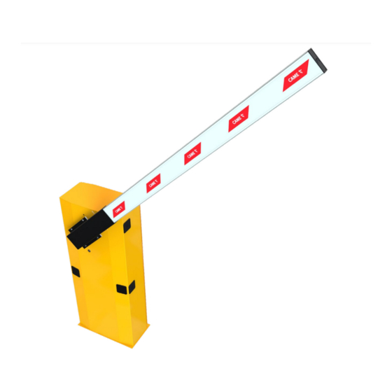
- Page 1 ÖZAK CAME.COM/OZAK Automatic barrier FA01581-EN - GARD series G6000T INSTALLATION MANUAL EN English...
- Page 3 - The figure shows which points constitute a potential hazard to people - G6000T anger of high voltage anger of hanD entrapment...
-
Page 4: Operating Limits
This automatic barrier is designed to operate in private and public parking facilities, in residential areas or in high traffic-volume areas. Do not install of use this device in any way, except as specified in this manual. OPERATING LIMITS Model G6000T Maximum clearance width of the passage (m) TECHNICAL DATA Model... -
Page 5: Description Of Parts
DESCRIPTION OF PARTS 1. Cabinet 7. Mechanical stops 2. Anchoring plate 8. Limit switch 3. Motor-shaft plate 9. Control panel 4. Release lock 10. Adjustable transmission rod 5. Gear motor 11. Anchoring braces 6. Balancing spring STANDARD INSTALLATION 1. Barrier with boom 7. -
Page 6: Preliminary Checks
GENERAL INSTRUCTIONS FOR INSTALLING ⚠ Only skilled, qualified staff must install this product. PRELIMINARY CHECKS ⚠ Before beginning, do the following: • make sure the plate is anchored to a solid spot; • checkthat there are no obstructions or impediments near the cabinet; • set up suitable tubes and conduits for the electric cables to pass through, making sure they are protected from any mechanical damage. - Page 7 INSTALLING ⚠ The following illustrations are mere examples. Consider that the space available where to fit the barrier and accessories will vary depending on the area where it is installed. It is up to the installer to find the most suitable solution. SETTING UP THE ANCHORING PLATE ⚠...
- Page 8 Fill the hole with earth around the concrete block. Remove the nut and washer from the bolts Fit the electric cables into the tubes so that they come out about 600 mm. SETTING UP THE BARRIER ⚠ Warning! Use hoisting equipment to transport and position the barrier. The mounting must be done by at least two people. During the initial mounting and fastening, the barrier may be unstable and could tip over.
- Page 9 Place the cabinet onto the anchoring plate and fasten it using nuts and washers. To change the rotation at a later date, request the documentation from your local retailer or contact Came in your Country (see the last page or visit www.came.com)
- Page 10 BALANCING THE BOOM The barrier is supplied with two Ø 50 mm springs (001G04060). The springs attach to lever arm (in the B-holes). Depending on how the barrier is finally configured, you may need to exclude one of the two springs or reattach it (see the table below). ⚠...
- Page 11 To precision balance the barrier, first release the gear motor and loosen the rod nut. Manually turn the spring to increase or reduce the traction. The boom should stabilize at 45°. Fit the nut to fasten the rod to the spring and tighten it. Lock the gearmotor once again.
-
Page 12: Control Panel
CONTROL PANEL ⚠ Caution! Before working on the control panel, cut off the mains power supply and remove any batteries. Power supply to the control panel and control devices: 24 V AC/DC. Use DIP switches to set functions and the trimmer for adjustments. All wiring connections are quick-fuse protected. -
Page 13: Electrical Connections
⚠ The electrical cables must not touch any heated parts such as the motor, transformer, and so on. FACTORY WIRING The gearmotor is already connected. To install the barrier on the right side, ask your local retailer for the documentation needed or contact Came in your country, see www.came.com 24 V DC gearmotor... -
Page 14: Control Devices
SIGNALING DEVICES Output to notify the state of the barrier (Contact rated for: 24 V AC - 3 W max.). it warns of the booms raised position, and switches off when the boom is lowe- red. Output for flashing light (Contact rated for: 24 V - 32 W max). It flashes when the boom is moving. -
Page 15: Safety Devices
SAFETY DEVICES Photocells Configure NC contact/s C1 and/or C5, input for safety accessories such as photocells. C1 reopening while closing. When the boom is closing, opening the contact causes its movement to invert until fully opened; If unused, shortcircuit contact 2-C1. C5 immediate closing. - Page 16 ESTABLISHING THE LIMIT-SWITCH POINTS Close the inspection hatch and power up the system. Move the boom the check that it is parallel to the road surface when closed and at about 89° when open. ⚠ The barrier's opening and closing maneuvers must be performed with the inspection hatch closed. For opening: - release the gearmotor;...
- Page 17 PROGRAMMING FUNCTIONS Default settings 1 2 3 4 5 6 7 8 9 10 3 4 5 6 7 8 9 10 DIP-SWITCH Description of functions 1 ON AUTOMATIC CLOSING; set 1 to OFF to deactivate it 2 ON ONLY OPEN from button 2-7 and/or from transmitter (with AF card fitted) 2 OFF OPEN-CLOSE-INVERT from the button on 2-7 and/or from a transmitter (with AF card fitted) 3 ON...
- Page 18 ACTIVATING THE RADIO CONTROL Connect the RG58 cable antenna cable to the corresponding terminals . For TOP and TAM series transmitting on 433.92 MHz, set the jumper-switch of the AF43S card as shown in the figure . Plug the AF card, that is, the AF43S or the AF868 into the connector on the control board . ⚠...
-
Page 19: Adjusting The Speed
ADJUSTING THE SPEED Min. = minimum Med. = medium Max. = maximum COM = common DIS. 27370 Max. Med. Min. Min. Max. To regulate the travel speed, move To adjust the slow-down speed, faston A on Min., Med. or Max. move faston B to Min. - Page 20 PAIRED CONNECTION WITH A SINGLE COMMAND Establish the MASTER, that is, the motor that drives both barriers, and SLAVE , that is, the motor piloted by the MASTER motor. SLAVE MASTER On the MASTER barrier's electronic board, make the necessary electrical connections, activate the radio control, program the functions and settings.
-
Page 21: Troubleshooting
Connect the two control boards using terminals RX-TX-GND as shown in the figure. Black Screened cable 2402C 22AWG-type cables Black RX TX GND E +10 -11 1 7 C1 C5 CONTROL BOARD SLAVE RX TX GND E +10 -11 1 7 C1 C5 CONTROL BOARD MASTER TROUBLESHOOTING... -
Page 22: Dismantling And Disposal
☞ CAME CANCELLI AUTOMATICI S.p.A. applies a certified Environmental Management System at its premises, which is compliant with the UNI EN ISO 14001 standard to ensure the environment is safeguarded. Please continue safeguarding the environment. At CAME we consider it one of the fundamentals of our operating and market strategies. Simply follow these brief disposal guidelines:... - Page 23 S.pA s' engage t>.en tondoo de la part des au?o<ites nationales, les renseignements relal!fs aux quas, machines/ Came S.pA se compromete a transmit,. como respuesta a una solicitud adecuadamente tundada por parte de las autondades naoonate. r,tormacion re' .acionat as...
- Page 24 The contents of this manual may change, at any time, and without notice. ÖZAK Geçiş Teknolojileri San. Tic. A.Ş. Köseköy, Çuhane Cd. No:130 41080 ÖZAK Kartepe - Kocaeli / Türkiye T & F +90 (0)262 373 48 48 (PBX) CAME.COM/OZAK...
Need help?
Do you have a question about the G6000T and is the answer not in the manual?
Questions and answers